Lighting device and projection-type display device using the same

a technology of projection-type display and light source device, which is applied in the direction of lighting and heating equipment, instruments, optics, etc., can solve the problems of projectors that are described in patent document 2 and the miniaturization of light source devices becomes problemati

Active Publication Date: 2013-08-22
SHARP NEC DISPLAY SOLUTIONS LTD
View PDF19 Cites 46 Cited by
  • Summary
  • Abstract
  • Description
  • Claims
  • Application Information

AI Technical Summary

Benefits of technology

[0026]It is an object of the present invention to provide a lighting device that is both compact and high-luminance i

Problems solved by technology

Depending on the configuration of the lighting device (in particular, the arrangement of each light source), the cooling means may become a large-scale structure, resulting in an increase in the size of the projector.
However, in the projector described in Patent Document 1, the light-emitting

Method used


Image

  • Lighting device and projection-type display device using the same
  • Lighting device and projection-type display device using the same
  • Lighting device and projection-type display device using the same

Examples


first exemplary embodiment

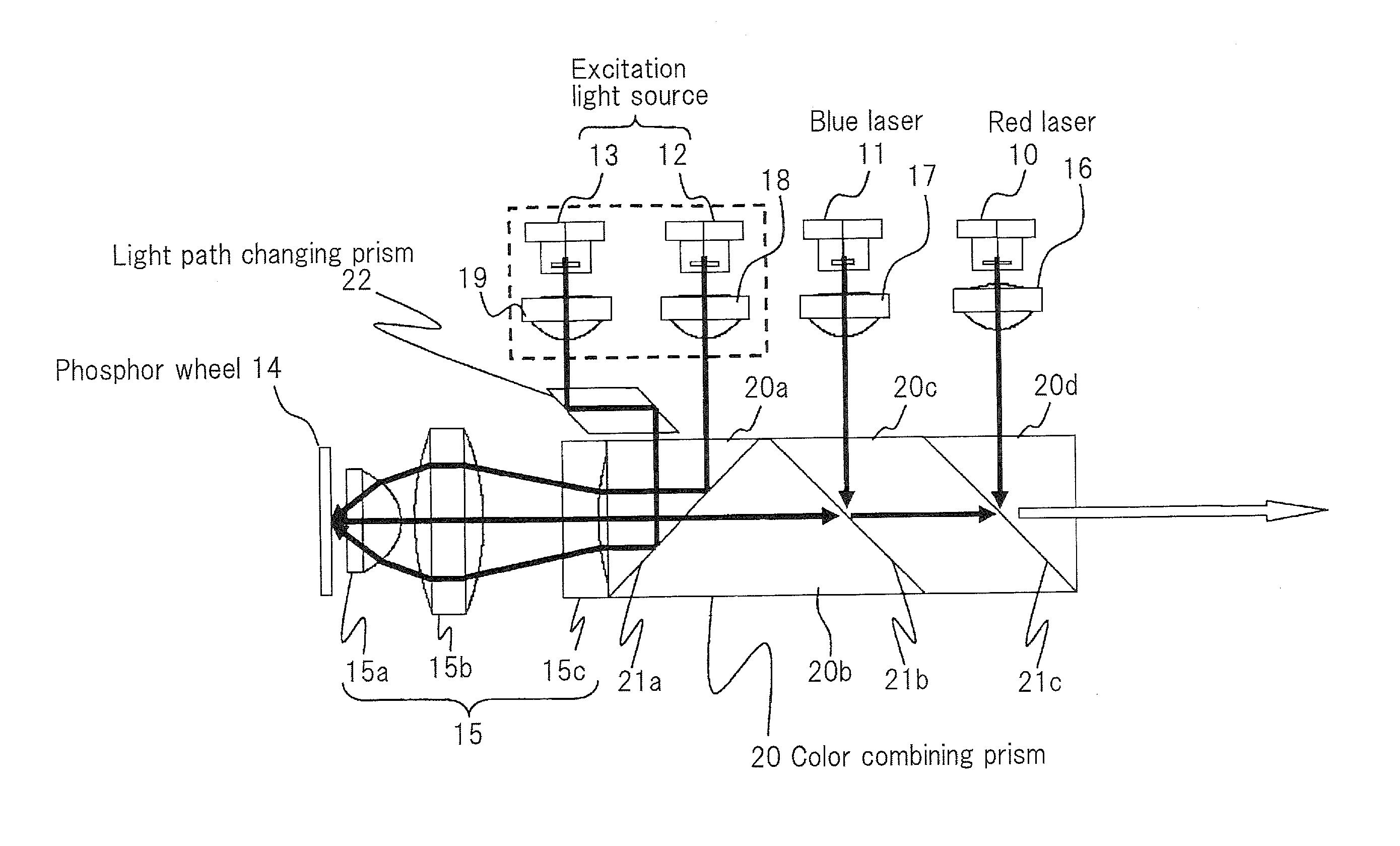
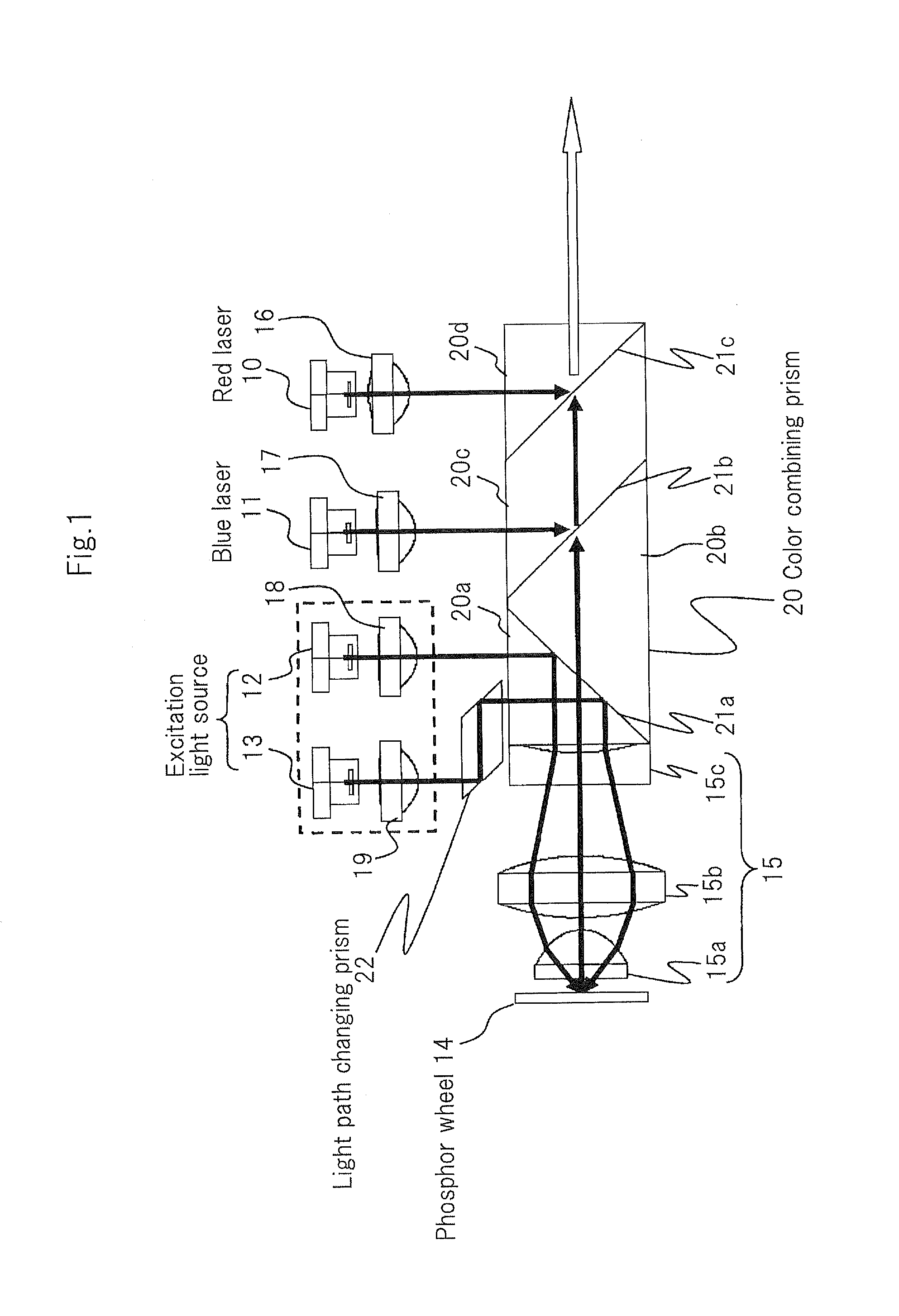
[0062]FIG. 1 is a schematic view showing the configuration of the lighting device that is the first exemplary embodiment of the present invention.

[0063]Referring to FIG. 1, the lighting device is a device that is used in a projection-type display device such as a projector and includes: red laser 10, blue laser 11, excitation light sources 12 and 13, phosphor wheel 14, collimator lenses 15-19, color-combining prism 20, and light path changing prism 21.

[0064]In FIG. 1, the light path of red laser light that is supplied from red laser 10, the light path of blue laser light that is supplied from blue laser 11, the light paths of excitation light that is supplied from excitation light sources 12 and 13, and the light path of green fluorescent light that is emitted from phosphor wheel 14 are shown by solid lines (heavy lines) with arrows. The white arrow is light in which the red laser light, blue laser light, and green fluorescent light are combined and is the output light of the lighti...

second exemplary embodiment

[0137]FIG. 10 is a schematic view showing the configuration of a lighting device that is the second exemplary embodiment of the present invention.

[0138]The lighting device of the present exemplary embodiment differs from the first exemplary embodiment in that it is equipped with dichroic mirrors 51a-51c in place of color-combining prism 20, and further, includes mirrors 52 and 53 in place of light path changing prism 22. The configuration is otherwise the same as the first exemplary embodiment (including modifications). In FIG. 10, the same reference numbers are given to constituent elements that are identical to those of the first exemplary embodiment.

[0139]Each of dichroic mirrors 51a-51c corresponds to dichroic surfaces 21a-21c, respectively, and all are composed of dielectric multilayer films.

[0140]Dichroic mirrors 51a-51c each cross the center ray of the luminous flux of green fluorescent light that is emitted from phosphor wheel 14, and moreover, are disposed orthogonal to the...


PUM


Abstract

A lighting device includes: a phosphor wheel; a color-combining prism including dichroic surfaces, the film surfaces of these dichroic surfaces being disposed to cross a center ray of luminous flux of fluorescence emitted from the phosphor wheel and to be orthogonal to a plane that contains the center ray; a blue laser; a red laser; and excitation light sources. When viewed from the direction perpendicular to the plane, the blue laser, red laser, and excitation light sources are arranged on one side of the center ray of the luminous flux of the fluorescence.

Description

TECHNICAL FIELD[0001]The present invention relates to the lighting device of a projection-type display device.BACKGROUND ART[0002]Patent Document 1 describes a projector that uses a phosphor as a light source.[0003]The principle parts of the projector described in Patent Document 1 are made up by a light source device, a cooling fan, a display element, and projection-side optics.[0004]The light source device includes a light-emitting device in which the fluorescent color is red, a light-emitting device in which the fluorescent color is green, a light-emitting device in which the fluorescent color is blue, and first and second dichroic mirrors that combine the fluorescent light of each color from these light-emitting devices.[0005]Each light-emitting device includes a cylinder-shaped rotating body in which a phosphor layer is formed on the outer periphery, a drive source that rotates the rotating body, a collimator lens that converts the fluorescent luminous flux emitted from the pho...

Claims


Application Information

Patent Timeline
IPC IPC(8): F21V13/02G03B21/16F21V29/02F21V13/12
CPCG03B21/204G03B21/2066G03B21/16F21V13/12F21V29/02F21V13/02G03B21/2013H04N9/3161H04N9/3164G03B21/208H04N9/3111G03B21/2033F21V29/83
Inventor MATSUBARA, MASATERU
Owner SHARP NEC DISPLAY SOLUTIONS LTD
Why Eureka
Try Eureka