Method of Interrogation of a Differential Sensor of Acoustic Type Having Two Resonances and Device Implementing the Method of Interrogation

a differential sensor and acoustic type technology, applied in the direction of thermometers, instruments, instruments, etc., can solve the drawback of requiring wide-band power detectors, relative low passband, and high noise, so as to eliminate the high frequency of the signal mixed and the effect of reducing the high frequency

Inactive Publication Date: 2013-08-22
SENSEOR
View PDF1 Cites 10 Cited by
  • Summary
  • Abstract
  • Description
  • Claims
  • Application Information

AI Technical Summary

Benefits of technology

[0013]Another advantage of the invention is that the latter can readily be implemented via a device of radio-modem type available on the market for a reasonable cost, and not dedicated specifically to applications of this type.
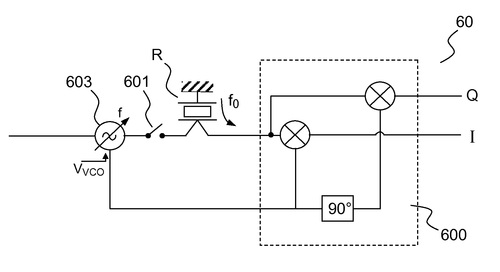
[0014]For this purpose, the subject of the invention is a method of interrogating a sensor comprising at least two resonators whose natural resonant frequency is dependent on a physical parameter, the method comprising a step of emitting an electromagnetic signal whose frequency is varied in a frequency band by increments of determined value, from a predetermined minimum value to a predetermined maximum value, the frequency band being split into two frequency sub-bands, each frequency sub-band containing at least the expected values respectively of each natural resonant frequency of the two resonators; a step of gathering a signal received as echo after a determined duration after the emission carried out in the emission step, for each frequency of the electromagnetic signal emitted; a step of transposing the signal received as echo to low frequency by mixing with a radiofrequency signal whose frequency equals the frequency of the electromagnetic signal emitted; a filtering step making it possible to eliminate the high frequencies of the signal mixed in the transposition step, a step of determining the difference between the respective natural resonant frequencies of the said two resonators, on the basis of the cross-correlation maximum of the characteristics constituted by the level of the signal received as echo for each frequency sub-band as a function of the frequency of the electromagnetic signal emitted.
[0015]In one embodiment of the invention, the cross-correlation maximum may be defined by the maximum value of the cross-correlation coefficient defined according to the relation:
[0016]In one embodiment of the invention, the narrowest sub-band may be supplemented with zeros for the interrogation frequency points situated outside of the measurement band, in such a way that the number of frequency points is identical for the two frequency sub-bands.
[0017]In one embodiment of the invention, the said difference between the natural resonant frequencies may be determined according to the relation: f2−f1=(t+M)·Δf, t denoting the frequency gap for which the cross-correlation coefficient is maximal.
[0018]The subject of the present invention is also a method of interrogating a sensor comprising at least two resonators whose natural resonant frequency is dependent on a physical parameter comprising a step of emitting an electromagnetic signal whose frequency is varied in a frequency band by increments of determined value, from a predetermined minimum value to a predetermined maximum value; a step of gathering a signal received as echo after a determined duration after the emission carried out in the emission step, for each frequency of the electromagnetic signal emitted; a step of transposing the signal received as echo to low frequency by mixing with a radiofrequency signal whose frequency equals the frequency of the electromagnetic signal emitted; a filtering step making it possible to eliminate the high frequencies of the signal mixed in the transposition step; a step of determining the difference between the respective natural resonant frequencies of the said two resonators, on the basis of the auto-correlation maximum of the characteristic constituted by the level of the signal received as echo.

Problems solved by technology

However, the relatively low passband is notably prejudicial to the signal-to-noise ratio, and therefore to the maximum interrogation distance.
A background issue related to the interrogation of SAW sensors thus pertains to the signal-to-noise ratio afforded by the method of interrogation.
This first technique presents notably the drawback of requiring wide-band power detectors, these devices being relatively complex and expensive.
This second technique presents notably the drawback of requiring significant calculation means.

Method used


Image

  • Method of Interrogation of a Differential Sensor of Acoustic Type Having Two Resonances and Device Implementing the Method of Interrogation
  • Method of Interrogation of a Differential Sensor of Acoustic Type Having Two Resonances and Device Implementing the Method of Interrogation
  • Method of Interrogation of a Differential Sensor of Acoustic Type Having Two Resonances and Device Implementing the Method of Interrogation

Examples


first embodiment

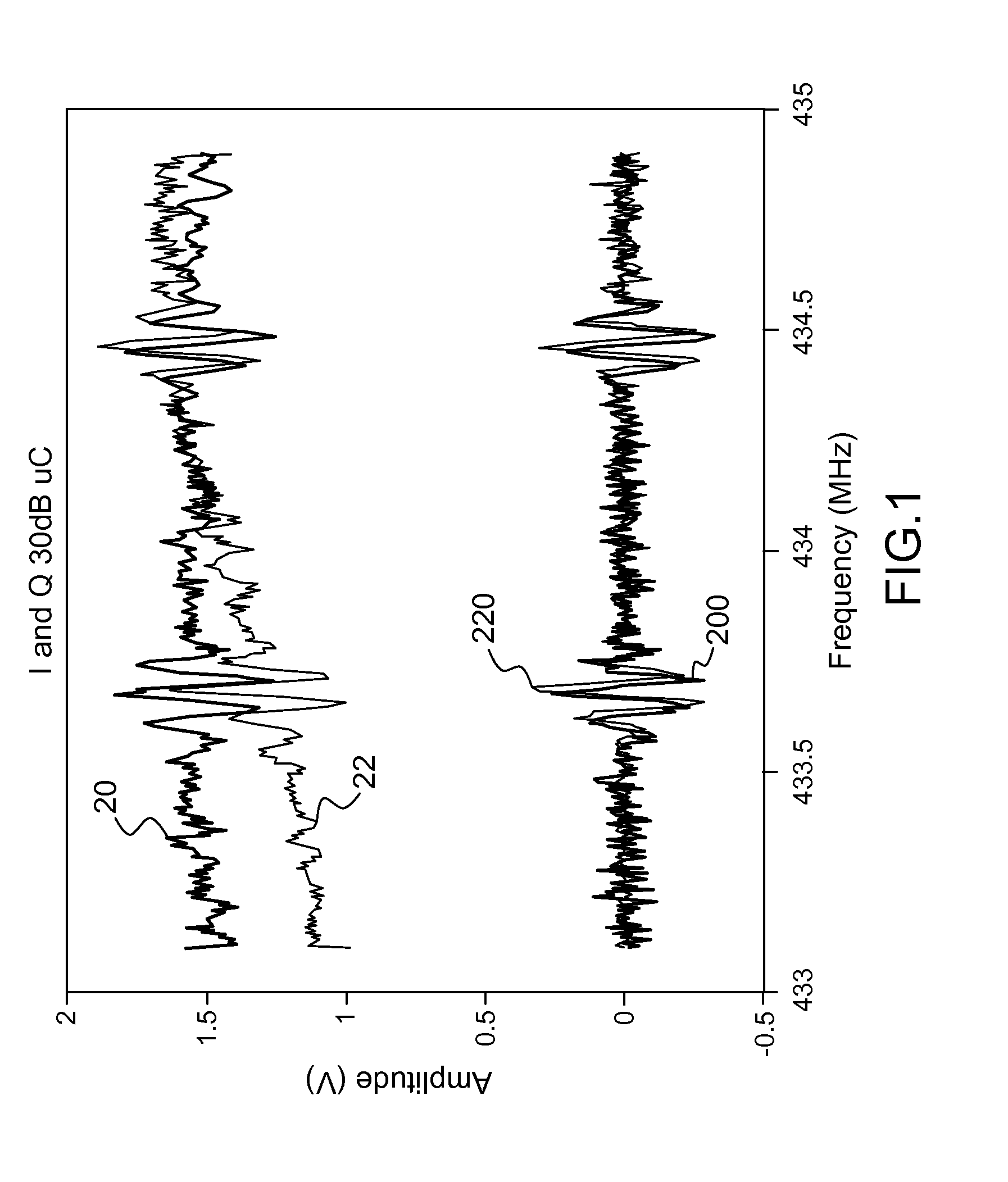
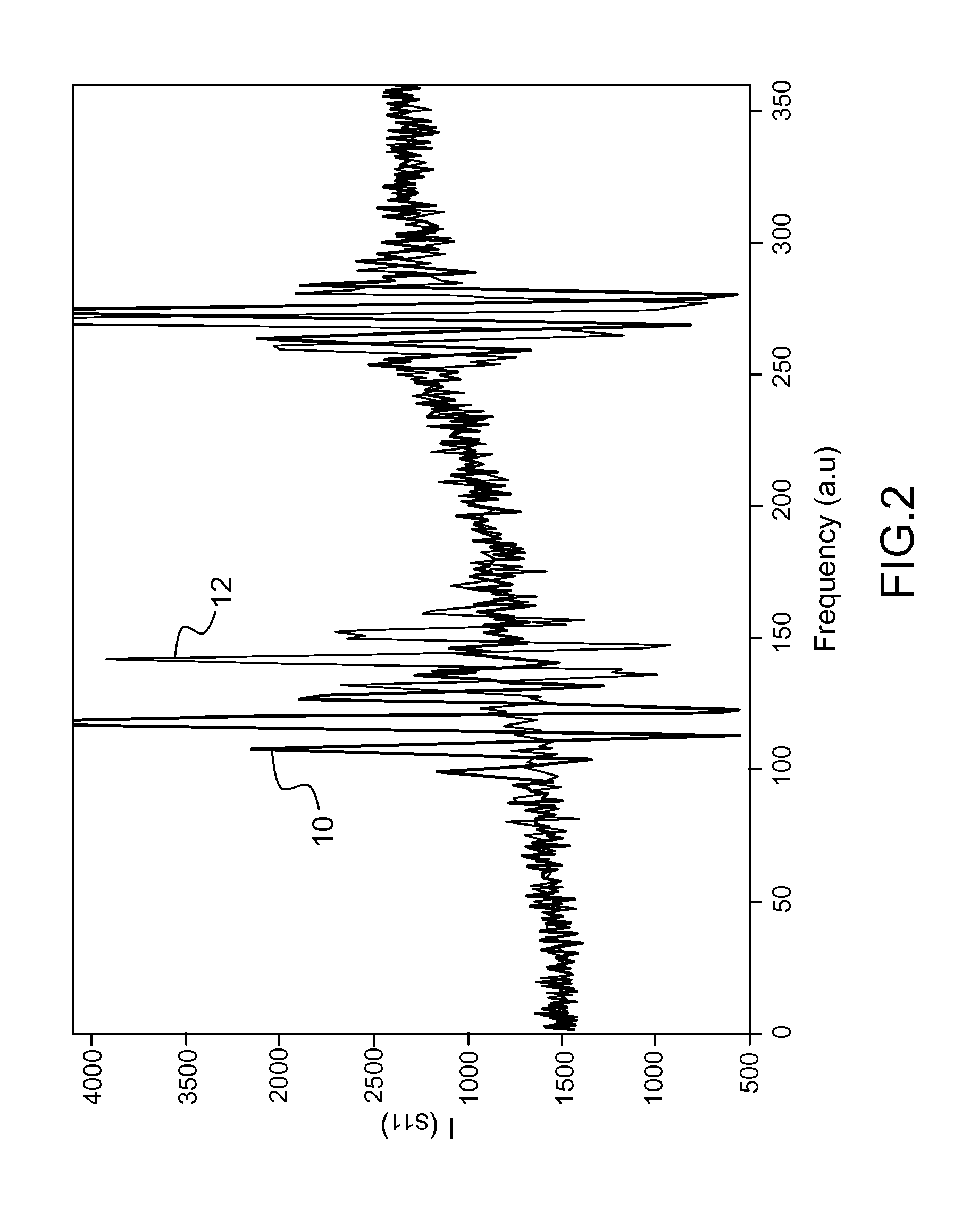
[0044]According to the invention, it is possible to determine the difference between the two natural resonant frequencies f1 and f2 by splitting the frequency domain in two sub-bands: a first frequency sub-band containing at least the natural resonant frequency f1 of the first resonator, and a second frequency sub-band containing at least the natural resonant frequency f2 of the second resonator. The two sub-bands may be chosen so that the characteristics of the level of the mixed and filtered signal are similar in the two sub-bands. The closer the quality factors exhibited by the two resonators forming the differential sensor, the greater the similarity of the spectral responses, a feature generally sought by designers of a differential sensor.

[0045]An estimator of the similarity between the characteristics of the level of the mixed and filtered signal in the two sub-bands may be formed by the cross-correlation coefficient defined by the following relation:

Xcorr(t)=∑k=-MMs1(k)s2(k-...

second embodiment

[0069]It should be noted that the example illustrated by FIG. 4 pertains to an interrogation method according to the first aforementioned embodiment, in which the variable frequency is varied in two distinct frequency sub-bands. In the case of the second embodiment described above, the frequency can be varied only in a single frequency band, in which case a single signal s(f) can be extracted during a single gathering step, not represented in the figure.

[0070]The second gathering step 403 can then be followed by a step 405 of calculating the correlation product of the signals s1(f) and s2(f). It should be noted that in the calculation step 405, in a similar manner the auto-correlation of the single signal s(f) can be calculated, in the case of the second embodiment described above.

[0071]On completion of the calculation step 405, it is possible to determine, by appropriate calculation means, the maximum value of the correlation product or of the auto-correlation, and to directly dedu...


PUM


Abstract

A method of interrogating a surface acoustic wave differential sensor formed by two resonators is provided, wherein the method allows the measurement of a physical parameter by determination of the difference between the natural resonant frequencies of the two resonators, which difference is determined on the basis of the analysis of a signal representative of the level of a signal received as echo of an interrogation signal, for a plurality of values of a frequency of the interrogation signal in a domain of predetermined values; the analysis can be based on the cross-correlation of the said signal representative of the level according to a splitting into two distinct frequency sub-bands. An advantage is that it may be implemented in a radio-modem.

Description

CROSS-REFERENCE TO RELATED APPLICATION[0001]This application claims priority to foreign French patent application No. FR 1157379, filed on Aug. 17, 2011, the disclosure of which is incorporated by reference in its entirety.FIELD OF THE INVENTION[0002]The present invention relates to a method of interrogating a differential sensor exhibiting at least two resonances having a sensitivity specific to one or more phenomena to be characterized. The present invention also relates to a device implementing such a method. It applies notably to passive differential sensors formed by a pair of resonators. These resonators can advantageously be of surface or bulk acoustic wave type.BACKGROUND[0003]A differential sensor may be formed by a pair of resonators, it being possible for each of the resonators to be made by depositing microstructures on the surface of a piezoelectric substrate. Such resonators belong to the family of components of surface acoustic wave type, commonly denoted “SAW” compon...

Claims


Application Information

Patent Timeline
Patent Type & Authority Applications(United States)
IPC IPC(8): G01R9/00
CPCG01R9/00G01D5/48G01K11/22G01H13/00
Inventor DROIT, CHRISTOPHEFRIEDT, JEAN-MICHELMARTIN, GILLESBALLANDRAS, SYLVAIN
Owner SENSEOR
Why Eureka
Try Eureka