
Diesel fuel system conditioning

a technology for diesel engines and fuel systems, applied in the direction of liquid fuel feeders, machines/engines, charge feed systems, etc., can solve the problems of affecting the service life of diesel engines, and causing a large number of pump warranty claims, so as to achieve the effect of reducing warranty costs and facilitating fuel filter replacemen

Active Publication Date: 2013-08-29
FORD GLOBAL TECH LLC
View PDF30 Cites 7 Cited by
  • Summary
  • Abstract
  • Description
  • Claims
  • Application Information

AI Technical Summary

Benefits of technology

The invention is about a system that improves the condition of diesel fuel in a vehicle's engine. It includes a fuel tank, a fuel filter, and a vacuum chamber. The system also includes a fuel recirculation valve that helps to melt wax that may accumulate in the filter and cause damage to the fuel system. The technical effects are that the fuel pump is protected from particles in the fuel, fuel filter replacement is easier, and fuel system performance is improved.

Problems solved by technology

However, this creates the disadvantage in that “dirty” fuel may be passed through the pump.
For example, downstream filters do not protect the pump adequately.
Is addition, a great many pump warranty claims are caused by plugged filters.
This, of course, is more expensive than warranted.
Another issue the inventors have recognized is that low pressure pumps may sometimes cause vibrations which may create excess noise and / or mechanical fatigue in the system.
Yet another issue that various embodiments may be configured to address is the presence water in the fuel which may otherwise be emulsified by the action of the pump.
Emulsified water is undesirable in that it may be passed to the engine combustion chamber in the fuel.
Another issue with diesel fuel filters, in particular at low ambient temperatures, such as during an engine cold-start, is that wax may precipitate out of the diesel fuel.
The precipitated wax may clog a fuel filter while also reducing the fluidity of the fuel.
As such, the precipitated wax in the fuel reduces the pressure of the low pressure fuel system and performance of the high pressure fuel system and, if severe enough, can cause damage to the fuel system.

Method used


Image

  • Diesel fuel system conditioning
  • Diesel fuel system conditioning
  • Diesel fuel system conditioning

Examples


Embodiment Construction

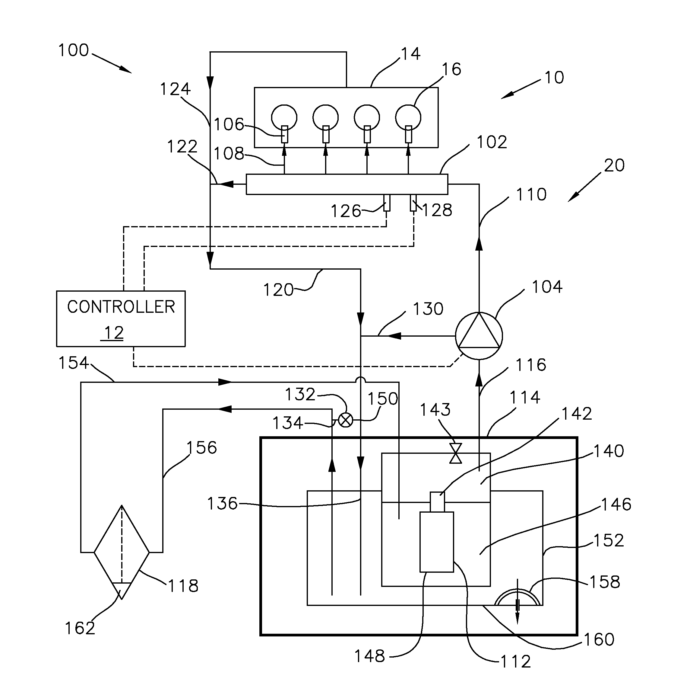
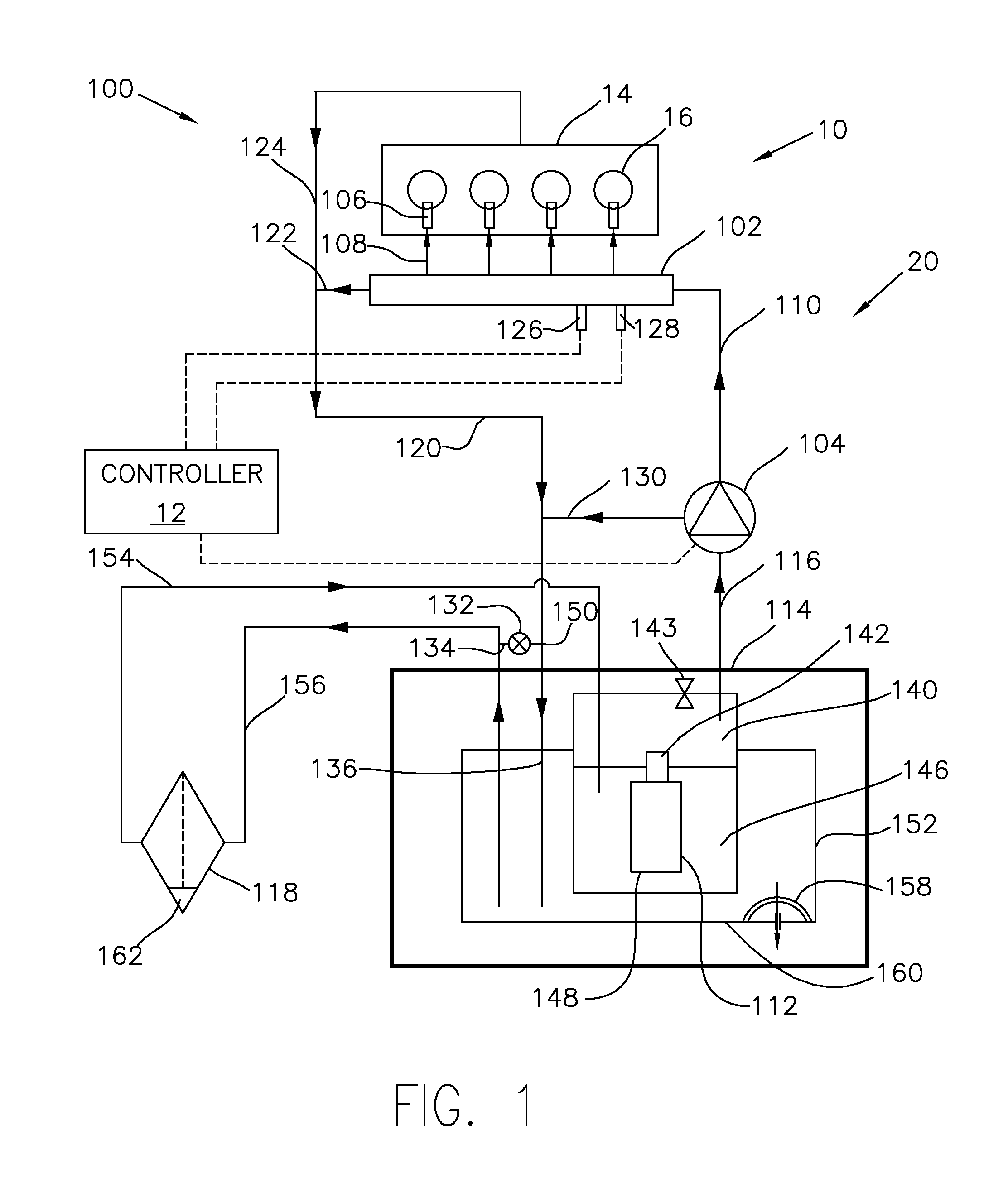
[0019]The following description relates to systems and methods for diesel fuel conditioning. FIG. 1 depicts an example vehicle system 100. In the depicted embodiment, vehicle system 100 is a diesel-fuelled vehicle system. The driving force of the vehicle system 100 may be generated by engine 10. Engine 10 may include one or more two banks 14. One bank 14 is indicated in the current example showing four cylinders 16. While engine 10 is shown as a 4-cylinder, four-stroke engine, it will be appreciated that the engine may have a different cylinder configuration (for e.g., in-line, V-shaped, or opposed) and / or a different number of cylinders (e.g., six, or eight).

[0020]Engine 10 of the vehicle system 100 may include a fuel system 20. Fuel system 20 may include a fuel rail 102, a supply pump 104, and fuel injectors 106. Fuel rail 102 may provide a chamber for holding fuel for subsequent injection into cylinders 16 through fuel injectors 106. In the depicted example, the fuel rail 102 may...


PUM


Abstract

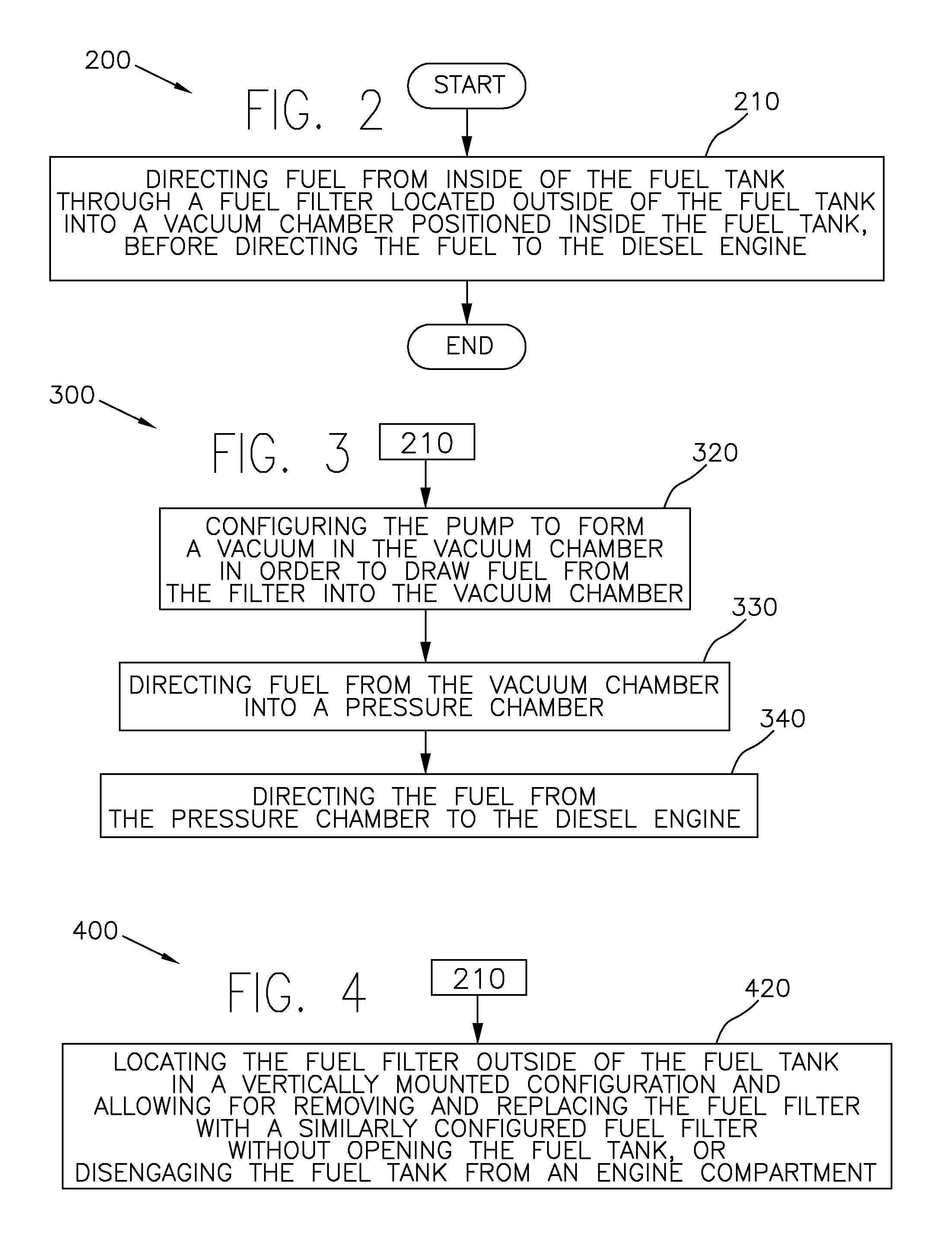
Methods and systems are provided for conditioning fuel for diesel engine. The system may include a fuel pump located within a fuel tank configured to pump fuel to the diesel engine. The system may also include a fuel filter located outside of the fuel tank operatively located upstream of a flow of fuel from the fuel pump. A method may include directing fuel from inside of the fuel tank through a fuel filter located outside of the fuel tank into a vacuum chamber positioned inside the fuel tank, before directing the fuel to the diesel engine.

Description

FIELD[0001]The present application relates to methods and systems for conditioning the fuel of a diesel engine, specifically methods and systems wherein a filter is located upstream of a low pressure fuel pump and which is located outside of the fuel tank.BACKGROUND AND SUMMARY[0002]Vehicle engines may be configured to operate using diesel fuels. Diesel fuel delivery and diesel fuel conditioning systems typically include a low pressure, or feed, pump functionally located with the fuel tank, and a high pressure pump functionally located relatively spaced from the fuel tank. There is also, typically, at least one fuel filter arranged to filter out particles which may be in the diesel fuel. It is common to locate the fuel filter downstream of the fuel pump. However, this creates the disadvantage in that “dirty” fuel may be passed through the pump. One such example is disclosed in U.S. Pat. No. 7,793,642 to Yonemoto et al.[0003]JP 2003-176761 discloses an alternative wherein a fuel filt...

Claims


Application Information

Patent Timeline
Patent Type & Authority Applications(United States)
IPC IPC(8): F02M37/04F02M37/24F02M37/32F02M37/54
CPCF02M37/22F02M2037/228F02M37/106F02M37/0047F02M37/50F02M37/54F02M37/24F02M37/32
Inventor ARMESTO, CARLOSSZYMUSIAK, SCOTT J.COOPER, SCOTT DONALDWOODRING, CHRISTOPHER ARNOLD
Owner FORD GLOBAL TECH LLC
Learn More