Additive fabrication technologies for creating molds for die components

a technology of additive manufacturing and molds, applied in additive manufacturing processes, foundry patterns, foundry moulding apparatus, etc., can solve the problems of inability to cast multiple die components using traditional sand casting methods, and the machining process lacks the precision needed to cast a near net-shape die componen

Inactive Publication Date: 2013-08-29
FORD MOTOR CO
View PDF2 Cites 49 Cited by
  • Summary
  • Abstract
  • Description
  • Claims
  • Application Information

AI Technical Summary

Benefits of technology

[0006]According to another aspect of the present invention, a method of making a die component includes the steps of forming a mold core package using an additive manufacturing process, wherein the mold core package comprises a negative image of the die component to be cast. A molten material is cast into the mold core package, and the molten material is cooled to form the die component having a near net configuration of the mold core package within an accuracy range of plus or minus 1 mm to 5 mm.
[0007]According to yet another aspect of the present invention, a method of making a plurality of sand mold packages for use...

Problems solved by technology

Thus, it is impractical to cast multiple die components using traditional sand casting methods, which involve tooling up a mold pattern to form a sand core from which the die component is cast.
This machining process lacks the precision needed to cast a near n...

Method used


Image

  • Additive fabrication technologies for creating molds for die components
  • Additive fabrication technologies for creating molds for die components
  • Additive fabrication technologies for creating molds for die components

Examples


Embodiment Construction

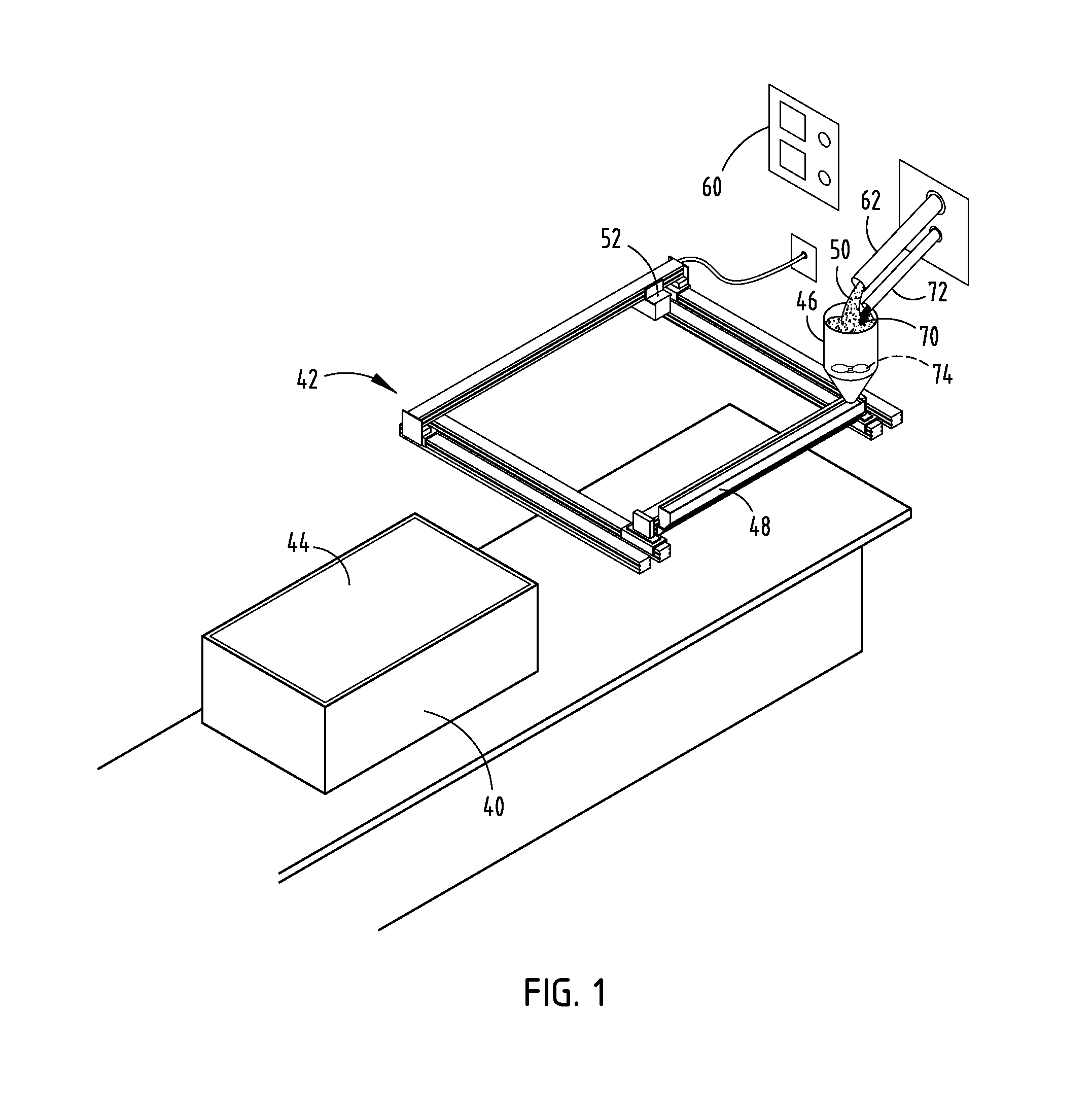
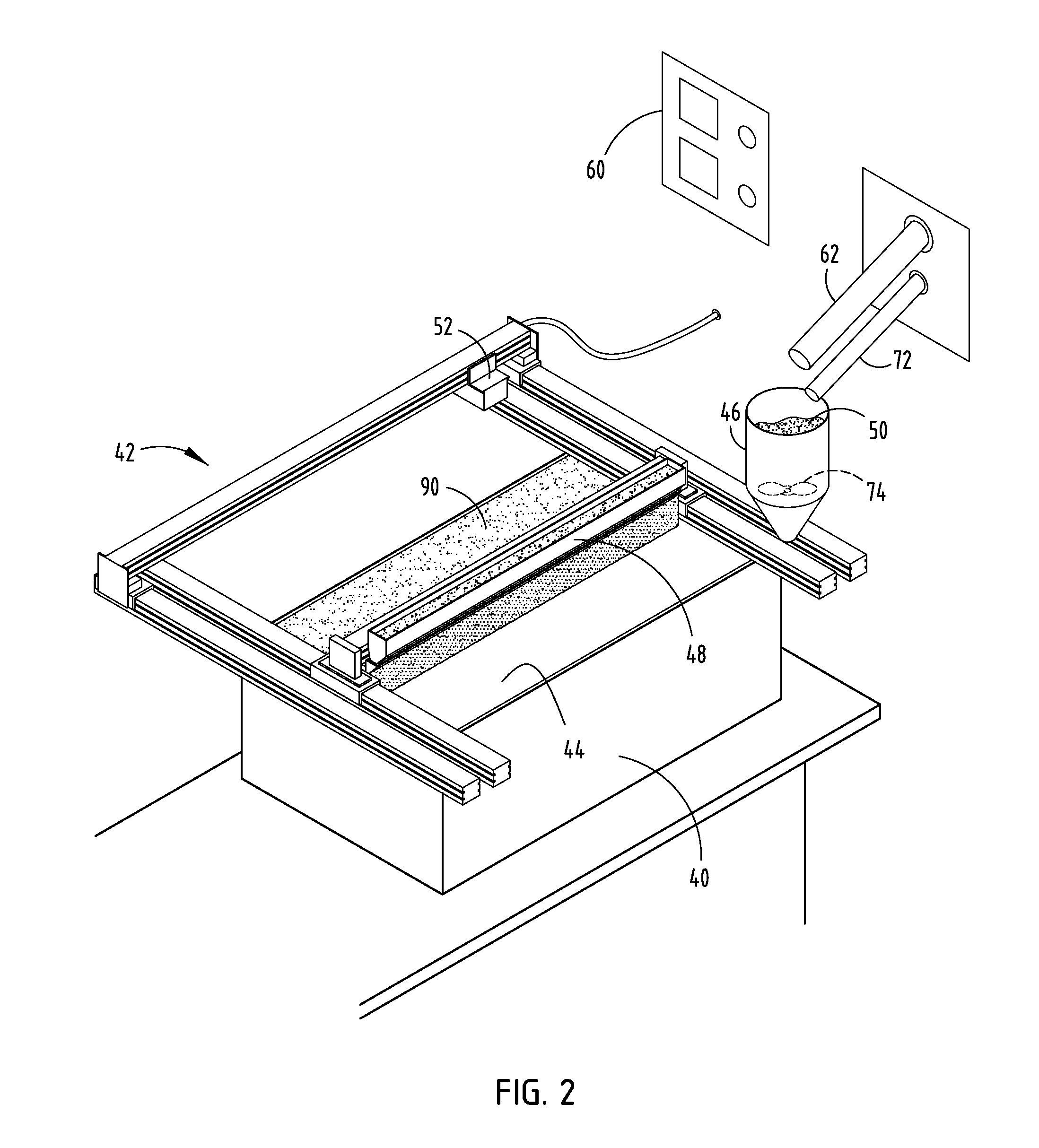
[0021]For the purposes of description herein, the terms “upper,”“lower,”“right,”“left,”“rear,”“front,”“vertical,”“horizontal,” and derivatives thereof shall relate to the invention as oriented in FIG. 1. However, it is to be understood that the invention may assume various alternative orientations, except where expressly specified to the contrary. It is also to be understood that the specific devices and processes illustrated in the attached drawings, and described in following specification, are simply exemplary embodiments. Hence, specific dimensions and other physical characteristics relating to the embodiments disclosed herein are not to be construed as limiting, unless expressly stated otherwise.

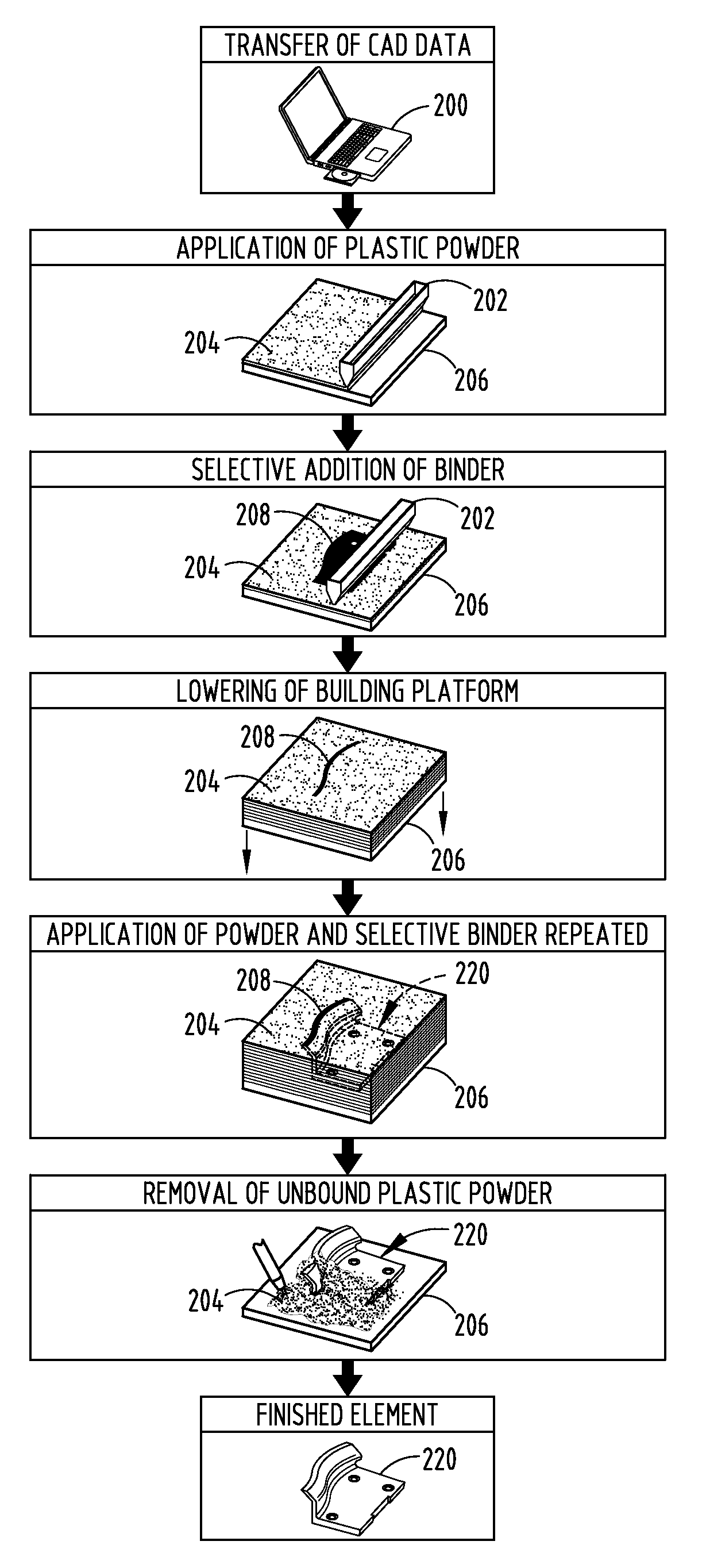
[0022]The present invention eliminates many steps in the process of making a die component due to its accuracy and automation, which saves a great deal of time, materials, and costs in the manufacturing of a die component. Using additive manufacturing or additive fabrication techniques,...


PUM

PropertyMeasurementUnit
Lengthaaaaaaaaaa
Lengthaaaaaaaaaa
Lengthaaaaaaaaaa

Abstract

A method comprising the use of additive manufacturing techniques for creating molds and pattern parts for subsequent use in the casting of die components and die shoes for use in die stamping processes.

Description

CROSS-REFERENCE TO RELATED APPLICATIONS[0001]This application is related to the following applications: U.S. patent application Ser. No. ______, filed on Feb. 29, 2012, entitled “MOLD CORE FOR FORMING A MOLDING TOOL” (Atty. Docket No. 83203377); U.S. patent application Ser. No.______, filed on Feb. 29, 2012, entitled “MOLDING ASSEMBLY WITH HEATING AND COOLING SYSTEM” (Atty. Docket No. 83203379); U.S. patent application Ser. No. ______, filed on Feb. 29, 2012, entitled “INTERCHANGEABLE MOLD INSERTS” (Atty. Docket No. 83203382); U.S. patent application Ser. No. ______, filed on Feb. 29, 2012, entitled “MOLD CORE PACKAGE FOR FORMING A POWDER SLUSH MOLDING TOOL” (Atty. Docket No. 83225801); and U.S. patent application Ser. No. ______, entitled “MOLDING TOOL WITH CONFORMAL PORTIONS AND METHOD OF MAKING THE SAME” (Atty. Docket No. 83225806), the entire disclosures of which are hereby incorporated herein by reference.FIELD OF THE INVENTION[0002]The present invention generally relates to th...

Claims


Application Information

Patent Timeline
IPC IPC(8): B22C9/04B22C9/10B22C9/02
CPCB22C9/04B22C9/06B29C67/0081B22C9/10B22F3/1055B22C9/08B29C64/165B33Y10/00B33Y80/00B29C64/182Y02P10/25B22F10/14B22F12/84B33Y70/10B22C9/12B22C9/18
Inventor SEARS, HAROLD P.KLOEB, JAMES TODDLIASI, EVANGELOSELLIS, LARRY EDWARDHASENBUSCH, RONALDPHILIPS, JOHNJACOBSON, ALAN LAWRENCE
Owner FORD MOTOR CO
Why Eureka
Try Eureka