Device for adjusting the height of a vehicle

a vehicle and height technology, applied in the field of lift systems, can solve the problems of reducing performance, affecting the performance of the vehicle, and affecting the performance of the vehicle so as to achieve the effect of reducing the cost of replacemen

a vehicle and height technology, applied in the field of lift systems, can solve the problems of reducing performance, affecting the performance of the vehicle, and affecting the performance of the vehicle so as to achieve the effect of reducing the cost of replacemen

US20130221626A1Active Publication Date: 2013-08-29STEALTH INNOVATIVE SYST

Image

  • Device for adjusting the height of a vehicle
  • Device for adjusting the height of a vehicle
  • Device for adjusting the height of a vehicle

Examples


Embodiment Construction

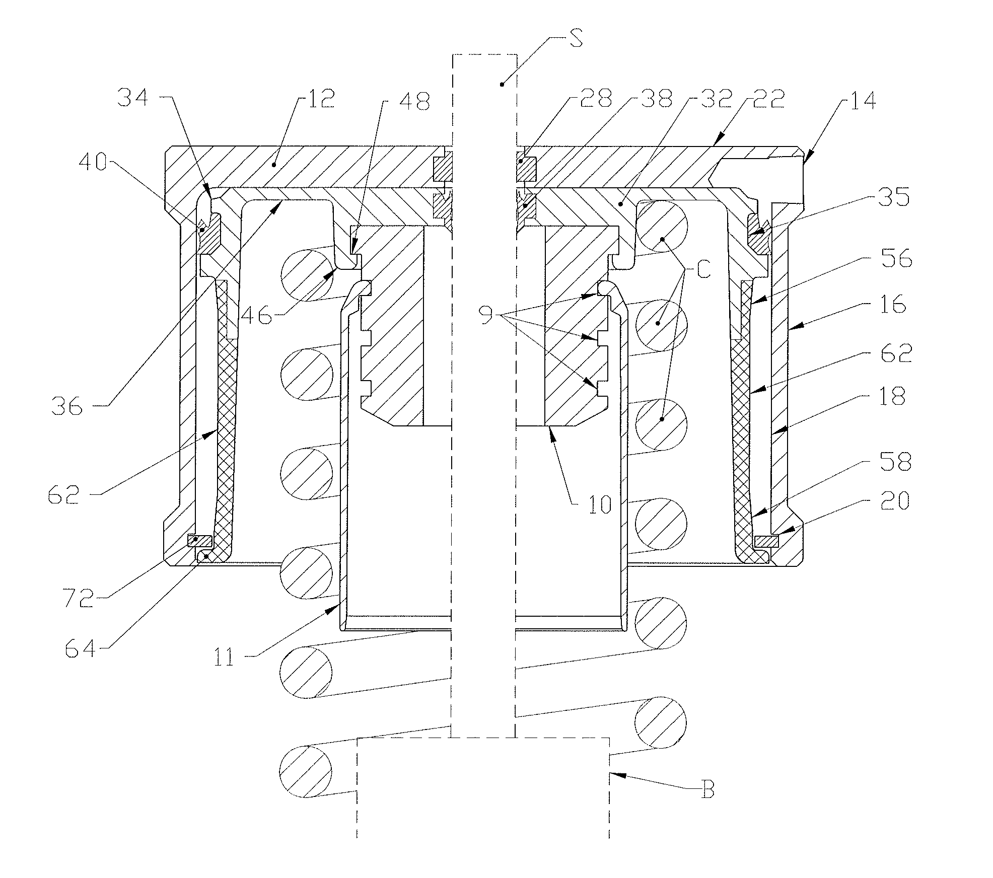
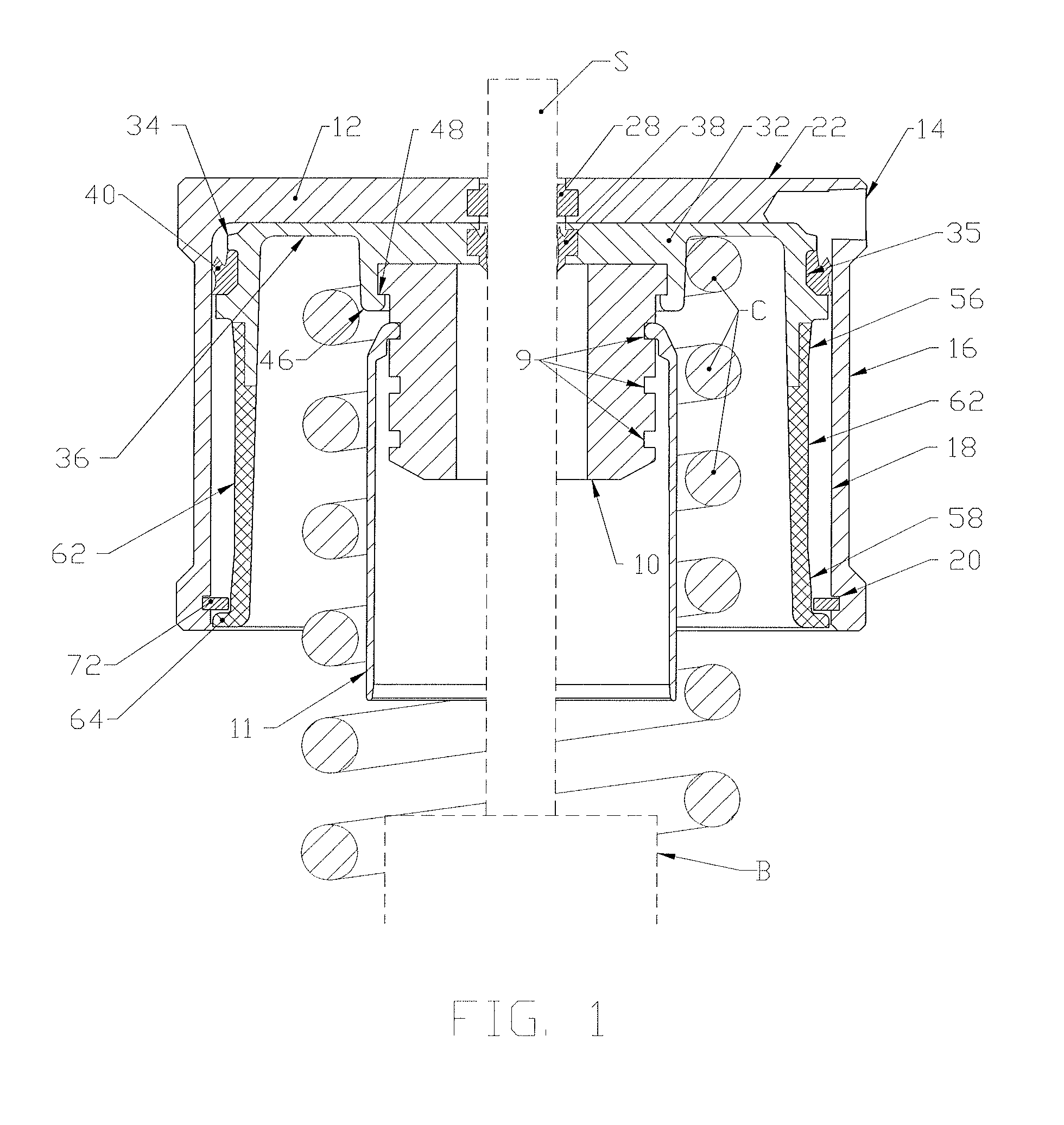
[0045]Referring to FIG. 1, shown is a longitudinal cross-sectional view of the presently preferred embodiment of the invention comprising a lifting device that is placed on a vehicle's shock absorber shaft S and coil spring C, but beneath the vehicle's chassis (or body). The circular top of the hollow cylinder rests against the vehicle's underbody (or chassis) to support the weight of the vehicle. A piston 32 is positioned inside the cylinder 22 and is proportioned for travel within the cylinder bore 18. The piston 32 is situated at the top of the coil spring C. The weight of the vehicle is supported by this coil spring C through the springs' contact with the pistons' spring perch section 36. The cylinder 22, piston 32, rubber or plastic bump stop 10, and dust shield 11 are coaxial with the shock absorber shaft S passing through the center of the cylinder 22, piston 32, rubber or plastic bump stop 10, and dust shield 11.

[0046]The cylinder 22 has circular cylinder top. There is an ap...


PUM


Abstract

The present invention is a system for adjusting the height of vehicles that have coil spring suspensions. The invention may be added to existing vehicle suspensions without the need to remove and replace the existing vehicle suspension components. The invention includes cylinders, pistons, seals, dust shields, pressure pump(s) and storage tank(s). It also may optionally include electronic hardware, such as, an electronic controller and software, to control the functions of the system and sensor(s) which detect ground clearance and speed. The invention may be operated manually by a vehicle driver through push buttons, which may operate through the vehicle's existing cruise control buttons. Alternatively, the system can be automated through an electronic control unit (ECU) to avoid collision with obstacles in the vehicle's path.

Description

[0001]This application claims the priority of U.S. provisional patent application No. 61 / 575,718 filed on Aug. 25, 2011.FIELD OF THE INVENTION[0002]This invention generally relates to lift systems, and more specifically, lift systems for adjusting the ground clearance of vehicles to avoid collisions with obstacles, such as speed bumps or sloping driveways, which can scrape and damage the underbody of a vehicle.BACKGROUND OF THE INVENTION[0003]Motor vehicle suspension systems have an inherent problem that results in various compromises. Vehicle suspension systems are generally designed to avoid obstacles anticipated to be in the vehicle's path. Some vehicles, such as off-road vehicles, are designed with a high ground clearance to avoid obstacles encountered in rugged terrain, while other vehicles are designed with low ground clearance for high speed performance and / or sportier appearance. Ground clearance is the amount of space between the base of an automobile tire and the underside...

Claims


Application Information

Patent Timeline
29 Aug 2013
Publication
US20130221626A1
IPC
B60G17/08
CPC
B60G17/08; B60G17/0272; B60G17/019; B60G2500/30; F16F9/00; F16F9/56; B60G17/0155; B60G17/052
Inventors
LEE, STEVEN DAVID