
Adaptive clock generating apparatus and method thereof

a clock generating apparatus and clock technology, applied in the direction of generating/distributing signals, pulse automatic control, frequency change manipulation, etc., can solve the problems of reducing the yield of the designed chip, affecting the production efficiency of the digital circuit, and affecting the efficiency of the design chip, so as to prevent the clock synchronization error of the circuit, improve the production efficiency of the digital circuit, and reduce the energy consumption

Active Publication Date: 2013-08-29
KOREA UNIV RES & BUSINESS FOUND
View PDF8 Cites 4 Cited by
  • Summary
  • Abstract
  • Description
  • Claims
  • Application Information

AI Technical Summary

Benefits of technology

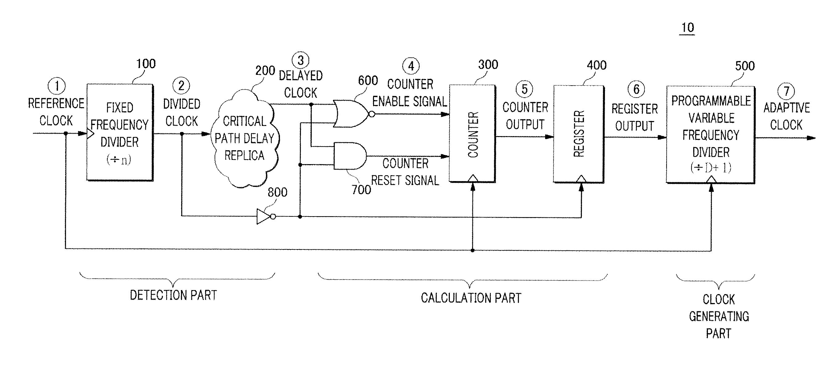
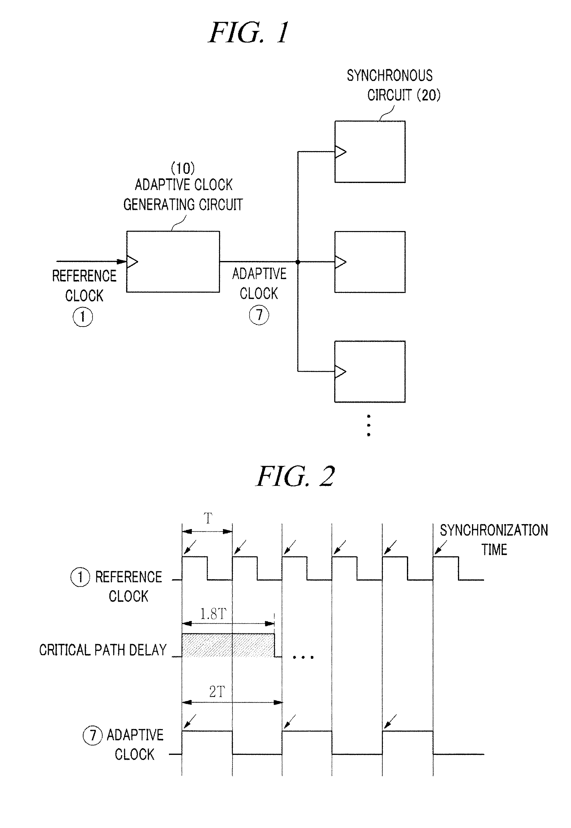
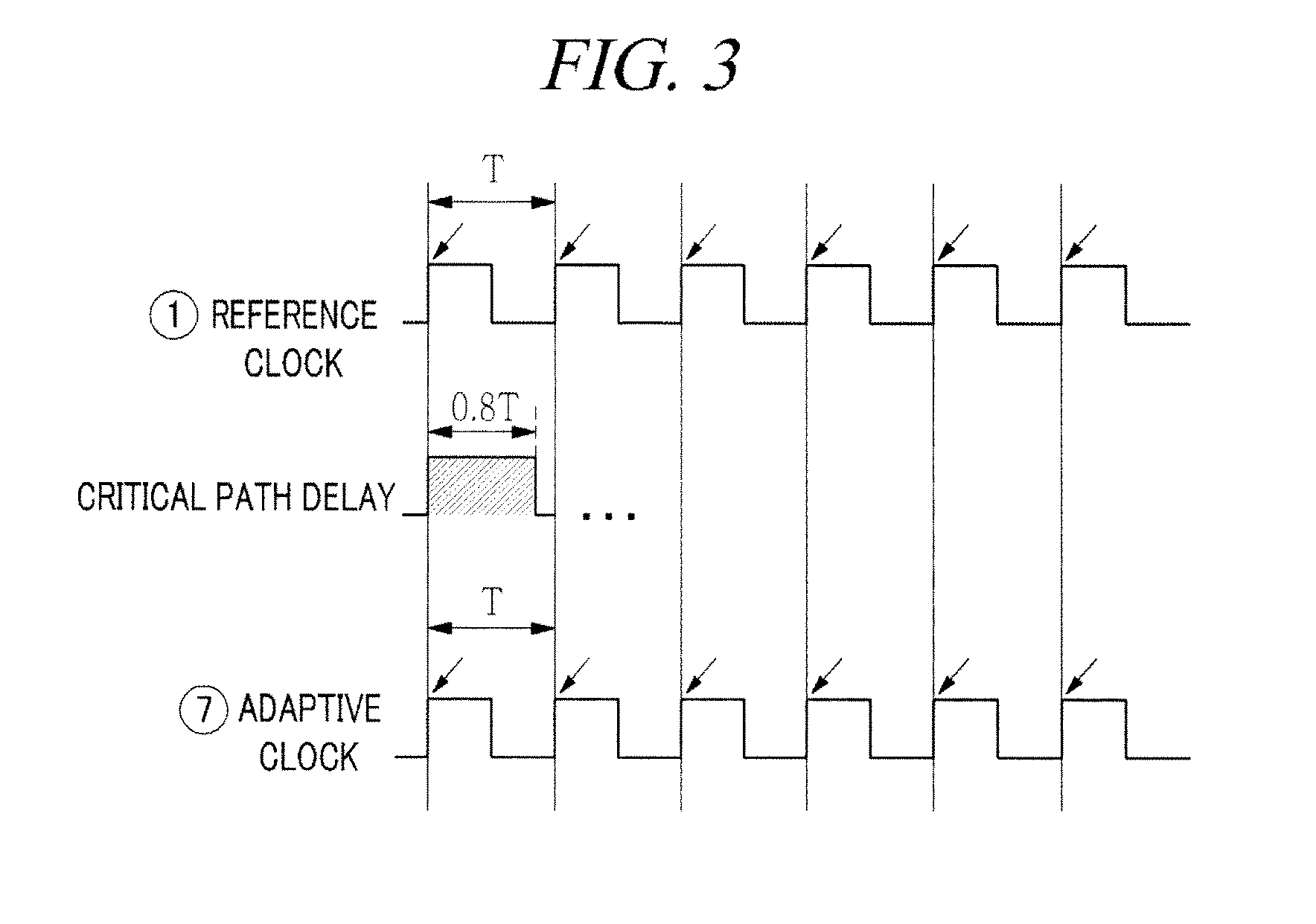
The present invention is an adaptive clock generating apparatus and method that can minimize energy consumption and prevent clock synchronization errors in a circuit. It improves production efficiency and product reliability by adaptively generating the clock frequency based on the operation conditions of the product. It uses simple elements such as a counter to calculate the best clock period. The invention also allows the synchronous circuit to operate as fast as possible as long as it does not malfunction.

Problems solved by technology

However, there is a problem in a sub / near-threshold operation that the performance of the circuit varies substantially compared to that in a super-threshold operation due to process variations, voltage fluctuations, and temperature variations.
The variation of the circuit performance results in issues in determining the circuit's clock signal frequency.
As a result, it will degrade the yield of the designed chip.
However, such an approach greatly increases energy consumption.
Since the period of the clock is set to the worst case, most circuits are usually in the idle state after finishing necessary operations, because the circuits are still left with as much time as the difference between the period of the clock and the actual critical path delay.
Even during that remaining time, a certain amount of current is still leaking.
Due to the energy consumed by the active leakage current, the goal to design a low power circuit is not sufficiently satisfied.
Since the circuit does not operate as fast as the potential speed of the circuit, time and other resources are wasted.
As described above, the problems of the malfunctioning of the circuit or the waste of energy become more serious as the supply voltage becomes lower due to temperature variation, variation of a supply voltage, and so on.

Method used


Image

  • Adaptive clock generating apparatus and method thereof
  • Adaptive clock generating apparatus and method thereof
  • Adaptive clock generating apparatus and method thereof

Examples


Embodiment Construction

[0029]Hereinafter, illustrative embodiments will be described in detail with reference to the accompanying drawings so that inventive concept may be readily implemented by those skilled in the art. However, it is to be noted that the present disclosure is not limited to the illustrative embodiments but can be realized in various other ways. In the drawings, certain parts not directly relevant to the description are omitted to enhance the clarity of the drawings, and like reference numerals denote like parts throughout the whole document.

[0030]Throughout the whole document, the terms “connected to” or “coupled to” are used to designate a connection or coupling of one element to another element and include both a case where an element is “directly connected or coupled to” another element and a case where an element is “electronically connected or coupled to” another element via still another element. Further, the term “comprises or includes” and / or “comprising or including” used in th...


PUM


Abstract

An adaptive clock generating apparatus is provided. The apparatus includes a fixed frequency divider, a replica, a counter, a variable frequency divider. The adaptive clock generating apparatus generates a clock whose period varies along with changes in the critical path delay of a synchronous circuit.

Description

CROSS-REFERENCE TO RELATED APPLICATION[0001]This application claims the benefit of Korean Patent Application No. 2012-0018814 filed on Feb. 24, 2012, which is incorporated herein by reference.FIELD OF THE INVENTION[0002]The present disclosure relates to an adaptive clock generating apparatus and a method thereof.BACKGROUND OF THE INVENTION[0003]In recent, with the explosive growth of the market for mobile electronic devices using batteries, demands for digital circuits requiring less power consumption are increasing.[0004]Power consumption of a digital circuit can be reduced by lowering its supply voltage. Upon usage, lowering the supply voltage to a level less than or near the threshold voltage of the semiconductor can minimize the power consumption of the circuit.[0005]However, there is a problem in a sub / near-threshold operation that the performance of the circuit varies substantially compared to that in a super-threshold operation due to process variations, voltage fluctuations,...

Claims


Application Information

Patent Timeline
Patent Type & Authority Applications(United States)
IPC IPC(8): H03L7/08
CPCH03L7/0802G06F1/10H03K5/00006H03K5/15H03L7/00
Inventor PARK, JONG SUNRIM, WOO JIN
Owner KOREA UNIV RES & BUSINESS FOUND
Learn More