Virtual image display apparatus

a display apparatus and virtual image technology, applied in the field of virtual image display apparatus, can solve the problems of reduced size and weight, unfavorable observer, image becomes very dark, etc., and achieve the effects of small size, high performance and wide viewing angl

Active Publication Date: 2013-08-29
SEIKO EPSON CORP
View PDF4 Cites 115 Cited by
  • Summary
  • Abstract
  • Description
  • Claims
  • Application Information

AI Technical Summary

Benefits of technology

[0013]An advantage of some aspects of the invention is to provide a virtual image display apparatus that has a see-through function of displaying external light and image light in an overlapping manner, having a wide viewing angle, high performance, a small size and a lightweight.
[0015]In the above-described virtual image display apparatus, since the intermediate image is formed inside the prism by the optical system or the like and the image light reflected in the order of the third surface, the first surface and the second surface then passes through the first surface to reach the observer, it is possible to realize a bright high-performance display with a wide viewing angle while thinning the prism to reduce the size and weight of the entire optical system. Further, with respect to external light, since the external light may pass through the first surface and the third surface to be observed and diopter at this time is about 0, it is possible to reduce defocusing or warp of the external light when the external light is observed in a see-through manner. Further, the prism has a shape along the face of the observer, the center of gravity may be close to the face, and a superior design may be achieved.
[0023]As the first surface and the third surface have the shapes satisfying the conditions (1) to (3), it is possible to favorably perform aberration correction of both the external light and the image light, and to obtain superior image quality.
[0025]In still another aspect of the invention, a half mirror is formed on the second surface to provide the image light to the observer, and a light transmitting member is integrally disposed on an outer side of the second surface so that diopter to the external light is about 0 to provide the external light and the image light to the observer in an overlapping manner. In this case, it is possible to reduce defocusing or warp of the external light observed outside the second surface.
[0032]In a further aspect of the invention, an interval between the first surface and the third surface is 5 mm or more and 15 mm or less. In this case, by setting the interval to be 5 mm or more, it is possible to sufficiently increase the size of the first prism that covers the front of the eyes, and by setting the interval to be 15 mm or less, it is possible to suppress increase in the weight.
[0033]In a still further aspect of the invention, an inclination angle of the second surface with respect to the first surface is 20° or more and 40° or less. In this case, by setting the inclination angle in this range, it is possible to easily cause the image light to enter the eyes with an appropriate number of reflections and an appropriate reflection angle.

Problems solved by technology

Further, if the field of view of the observer is entirely covered and thus only image light is viewed, an external scene is not viewed by the observer, which may cause uneasiness for the observer.
However, in the case of the optical system disclosed in Japanese Patent No. 2746697, the projection lens is large in size, which prevents a reduction in size and weight.
However, the optical system disclosed in Japanese Patent No. 3787399 has no consideration of allowing the observer to view an external scene.
However, since image light is reflected on the half mirror surface twice, an image becomes very dark.
However, in order to view an external scene by applying the optical system disclosed in Japanese Patent No. 4218553, it is necessary to attach a compensation lens onto the concave mirror, which generally increases the thickness.
However, in the case of the optical system disclosed in Japanese Patent No. 4819532, a convex portion at the center of a prism or a projection lens obstructs the field of view.
Thus, even though there is no problem in observation of the external light, it is difficult to effectively correct aberration of the image light.
Further, below a lower limit of the condition (1), the curvature is excessively strong.
Thus, it is difficult to perform aberration correction, and since the position of the prism is close to the face, the fit deteriorates.
Beyond an upper limit of the condition (2), astigmatism occurring on the third surface is excessively large, and thus, it is difficult to perform aberration correction.
In general, if an error of distant diopter exceeds ±1D, this causes discomfort.

Method used


Image

  • Virtual image display apparatus
  • Virtual image display apparatus
  • Virtual image display apparatus

Examples


example 1

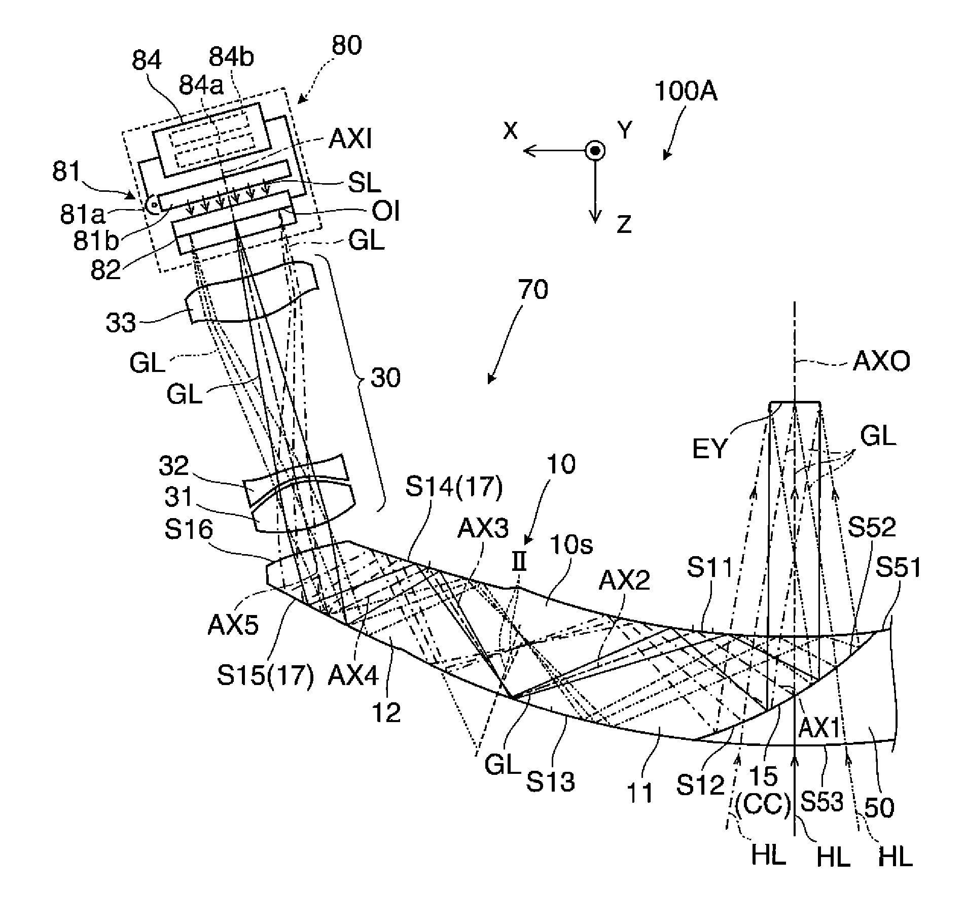
[0115]In a projection see-through device of Example 1, data on an optical surface that forms a prism and a projection lens is shown in Table 1. For example, FFS1 represents the first surface S11, FFS2 represents the second surface S12, and FFS3 represents the third surface S13. Further, ASP1 represents an exiting surface of a first lens of the projection lens, and ASP2 represents an incident surface of the first lens.

TABLE 1NoTypeRTNdVd1SPH∞22.002FFS1−76.7895.501.52555.953FFS2−45.250−5.501.52555.954FFS1−76.78910.001.52555.955FFS3−86.789−20.001.52555.956FFS4−152.63611.001.52555.957FFS5−104.492−6.501.52555.958FFS638.430−2.009ASP1−11.866−4.381.52555.9510ASP27.425−0.5011ASP36.090−1.001.58529.9012ASP422.664−14.5513ASP5−8.433−4.001.52555.9514ASP6−17.659−3.7315SPH∞−1.601.45867.8216imagesurface

[0116]With respect to the optical surface in the prism that forms Example 1, the optical axis inclination angle (tilt) TLY on the cross section and the optical axis deviation (decenter) DCX are shown ...

example 2

[0125]In a projection see-through device of Example 2, data on an optical surface that forms a prism and a projection lens is shown in Table 5.

TABLE 5NoTypeRTNdVd1SPH∞22.002FFS1−121.6585.501.52555.953FFS2−49.762−5.501.52555.954FFS1−121.65810.001.52555.955FFS3−131.658−20.001.52555.956FFS4−148.18714.001.52555.957FFS5−193.512−10.001.52555.958FFS616.102−2.009ASP1−20.674−7.001.52555.9510ASP29.056−0.5011ASP37.190−1.001.58529.9012ASP454.244−19.3713ASP5−10.384−8.151.52555.9514ASP6−23.928−4.9815SPH∞−1.601.45867.8216imagesurface

[0126]With respect to the optical surface in the prism that forms Example 2, the optical axis inclination angle (tilt) TLY on the cross section and the optical axis deviation (decenter) DCX are shown in Table 6.

TABLE 6TLY (beforeDCX (afterTLY (afterNoTypesurface)surface)surface)2FFS10003FFS2−290294FFS10005FFS3024.171−39.586FFS4500507FFS5−500−508FFS6000

[0127]With respect to each optical surface in the prism that forms Example 2, a coefficient in a polynomial expansion o...

example 3

[0132]In a projection see-through device of Example 3, data on an optical surface that forms a prism and a projection lens is shown in Table 9.

TABLE 9NoTypeRTNdVd1SPH∞20.002FFS1−82.3795.501.52555.953FFS2−44.857−5.501.52555.954FFS1−82.37910.001.52555.955FFS3−90.616−20.001.52555.956FFS467.06210.001.52555.957FFS569.676−10.001.52555.958FFS467.062−0.509ASP1−6.137−6.001.52555.9510ASP26.711−0.5011ASP36.613−1.201.58529.9012ASP4−17.825−6.0013ASP5−7.024−6.001.52555.9514ASP632.129−3.9115SPH∞−1.601.45867.8216imagesurface

[0133]With respect to the optical surface in the prism that forms Example 3, the optical axis inclination angle (tilt) TLY on the cross section and the optical axis deviation (decenter) DCX are shown in Table 10.

TABLE 10TLY (beforeDCX (afterTLY (afterNoTypesurface)surface)surface)2FFS10003FFS2−280284FFS10005FFS3023.17−44.196FFS4530537FFS5−350−358FFS4010−17.78

[0134]With respect to each optical surface in the prism that forms Example 3, a coefficient in a polynomial expansion of a...


PUM


Abstract

An intermediate image is formed inside a prism by a projection lens and the like. Image light, totally reflected, in the order of a third surface, a first surface and a second surface, on two or more surfaces thereof, reaches an eye of an observer after passing through the first surface. Thus, it is possible to decrease the thickness of the prism and to reduce the size and weight of the entire optical system. Further, it is possible to realize a bright high-performance display with a wide viewing angle. With respect to external light, it is possible to pass the external light through the first surface and the third surface, for example, for observation. Further, by setting diopter at this time to about 0, it is possible to reduce defocusing or warp of the external light when the external light is observed in a see-through manner.

Description

BACKGROUND[0001]1. Technical Field[0002]The present invention relates to a virtual image display apparatus that provides an image formed by an image display element or the like to an observer, and more particularly, to a virtual image display apparatus that is suitable for a head-mounted display mounted to the head of the observer.[0003]2. Related Art[0004]A variety of optical systems have been proposed as an optical system that is assembled in a virtual image display apparatus such as a head-mounted display (hereinafter, referred to as an HMD) mounted to the head of an observer (refer to Japanese Patent Nos. 2746697, 3787399, 4218553 and 4819532).[0005]With respect to the virtual image display apparatus such as an HMD, it is desirable to enlarge a viewing angle of image light and to reduce the weight of the apparatus. In particular, in order to improve the fit, it is important to decrease the thickness in a visual axis direction of an observer and to make the center of gravity clos...

Claims


Application Information

Patent Timeline
Patent Type & Authority Applications(United States)
IPC IPC(8): G02B27/01
CPCG02B2027/0123G02B17/0848G02B27/0172G02B27/017G02B27/0101G02B17/086
Inventor KOMATSU, AKIRATOTANI, TAKAHIROTAKEDA, TAKASHIMIYAO, TOSHIAKITAKAGI, MASAYUKI
Owner SEIKO EPSON CORP
Why Eureka
Try Eureka