Power Conversion Device

a power conversion device and power conversion technology, applied in ac network circuit arrangements, dc-ac conversion without reversal, active power filtering, etc., can solve the problems of increasing the number of bits of the control signal frame, increasing the cost of optical fiber cable having a dielectric strength, and increasing the cost of optical fiber cable. , to achieve the effect of low cost and easy inability to transmi

Active Publication Date: 2013-08-29
HITACHI LTD
View PDF8 Cites 47 Cited by
  • Summary
  • Abstract
  • Description
  • Claims
  • Application Information

AI Technical Summary

Problems solved by technology

Further, as there is a possibility of a communication error such as a cable short circuit due to insulation deterioration, a feature to detect such a communication error need to be also provided.
However, there is a problem that the number of bits of the control signal frame increases when the communication error detection feature is incorporated into the control signal frame, and it takes longer time.
An optical fiber cable having a dielectric strength is more expensive as an insulation performance increases.

Method used


Image

  • Power Conversion Device
  • Power Conversion Device
  • Power Conversion Device

Examples


first embodiment

[0023]A first embodiment of the present invention will be described with reference to FIGS. 1 to 3.

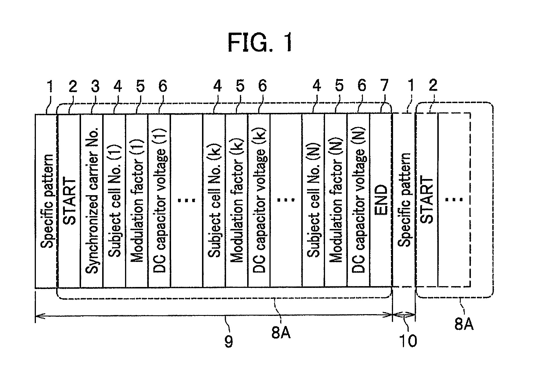
[0024]FIG. 1 is a diagram showing a configuration of an optical serial signal frame provided with a control signal and a specific pattern signal used for the first embodiment of the present invention.

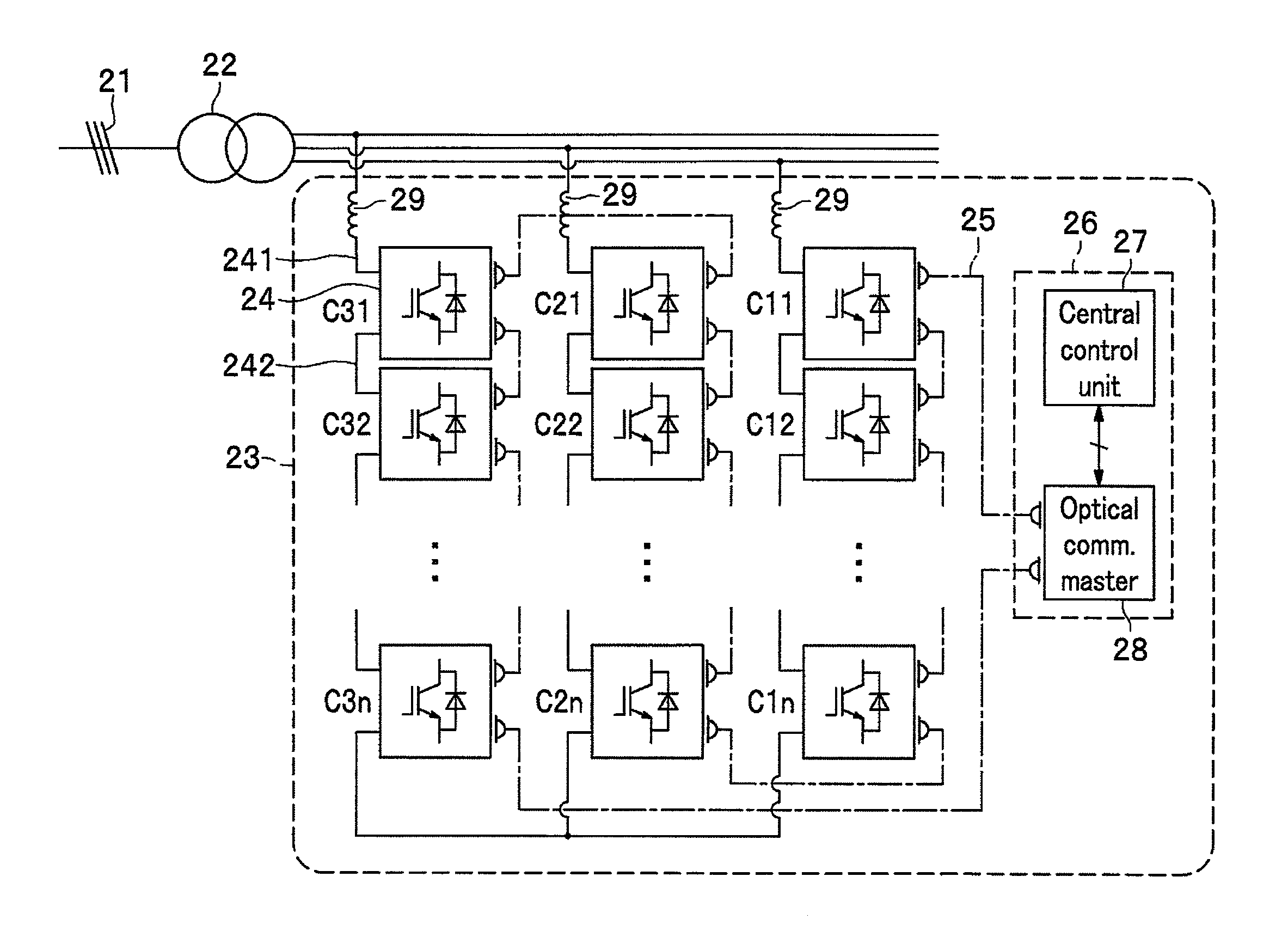
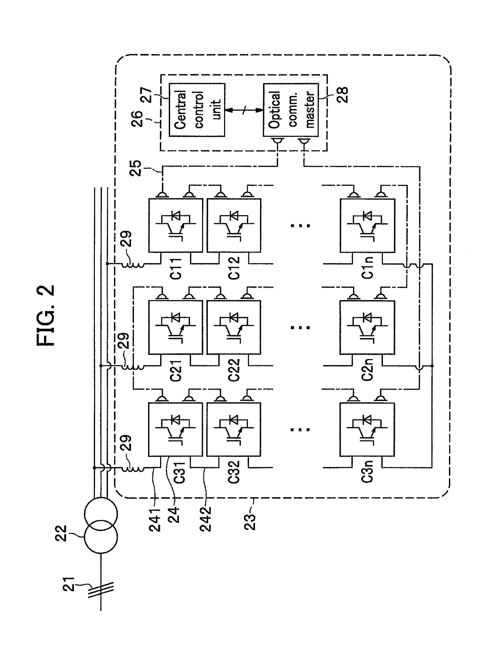
[0025]FIGS. 2 and 3 are diagrams showing circuit configurations of a cascade-connection type SVC which is a power conversion device that applies the optical serial signal frame used in the first embodiment of the present invention.

[0026]A feature of the first embodiment of the present invention is in the configuration of an optical serial signal frame provided with a control signal and a specific pattern signal in FIG. 1, but for the purpose of easy understanding why such a configuration of a signal frame is being applied, a circuit configuration of a power conversion device that applies an optical serial signal frame used in the first embodiment of the present invention will be described ...

second embodiment

Second Usage of Second Embodiment

[0080]Next, a second usage of the second embodiment will be described. As in the first usage of the second embodiment, the control signal frame 8B in the second usage of the second embodiment is the configuration shown in FIG. 4.

[0081]In the first usage of the second embodiment, the communication error presence signal 12 indicating the presence of an error at an upstream cell and the communication error cell number 13 were made to have the same signals, regardless of the communication error detection result for the specific pattern 1 at the (k+1)-th cell and beyond.

[0082]However, in the second usage of the second embodiment, by rendering a specific pattern 1 of a new control signal frame to be transmitted from the k-th cell same as the specific pattern 1 to be transmitted when there is no communication error, a communication error detected at the (k+1)-th cell and beyond due to not receiving the specific pattern 1 or inconsistency thereof is assumed ...

third embodiment

[0085]Next, a third embodiment of the present invention will be described.

[0086]FIG. 5 is a diagram showing a configuration of an optical serial signal frame including a common-for-all-cell control signal 14 in the third embodiment.

[0087]The control signal frame 8C in FIG. 5 is obtained by including the common-for-all-cell control signal 14 into the control signal frame 8A that does not contain a synchronization pattern shown in the first embodiment. A specific pattern 1 is provided between pluralities of the control signal frames 8C.

[0088]At the k-th cell, when a communication error due to not receiving the specific pattern 1 or inconsistency between the received signal and the specific pattern 1 is detected, the control signal is set to turn off the switching elements (35A, 35B, 36A, 36B, FIG. 3) of each of the cells (24, FIG. 2) in the common-for-all-cell control signal 14, and a new control signal frame is generated, then the new control signal frame is transmitted to the (k+1)-...


PUM


Abstract

A power conversion device includes: a plurality of cascade-connection type single-phase power converters; and a central control unit that controls the plurality of the single-phase power converters, wherein each of the plurality of single-phase power converters has a single-phase power converter control unit, and the central control unit and the plurality of the single-phase power converter control units are connected via a communication means having a daisy-chain configuration, wherein the single-phase power converter control unit transmits and receives a control signal via the communication means having the daisy-chain configuration, as well as a specific pattern signal, other than a control signal frame, which can be distinguished from the control signal frame, and determines a communication error due to not receiving the specific pattern signal at the single-phase power converter control unit, or an inconsistency between the received signal and the specific pattern signal.

Description

CROSS REFERENCE TO RELATED APPLICATION[0001]The present application claims benefit of the filing date of PCT Application No. PCT / JP2011 / 074523 filed on Oct. 25, 2011 which is incorporated herein by reference.TECHNICAL FIELD[0002]The present invention relates to a power conversion device, and a control and communication device as well as a communication error detecting method, both of which are used for the power conversion device.BACKGROUND OF INVENTION[0003]In recent years, the introduction of distributed power sources, typified by a solar power generation, into the power distribution system has been actively promoted, but as a result, increasing voltage variation of the power distribution system is becoming a problem. It is effective to apply a reactive power compensator for improving the stability of such a power distribution system, and in particular, application of a cascade-connection type SVC (Static Var Compensator) is proposed.[0004]In Japanese Patent Application JP2007-280...

Claims


Application Information

Patent Timeline
Patent Type & Authority Applications(United States)
IPC IPC(8): H02M7/217
CPCH02J3/1857H02M7/49Y02E40/26H02M7/217H02M1/0845H02M2007/4835Y02E40/20H02M7/4835
Inventor TSUCHIYA, MITSUYOSHIINOUE, SHIGENORIKATO, TETSUYASODEYAMA, TADASHI
Owner HITACHI LTD
Why Eureka
Try Eureka