Battery assembly

a battery and assembly technology, applied in the field of battery assembly, can solve the problems of difficult to hold the cells in place properly, difficult to produce final products, and high electrical losses, and achieve the effect of cost-effective production

Inactive Publication Date: 2013-08-29
ALELION ENERGY SYST AB
View PDF5 Cites 25 Cited by
  • Summary
  • Abstract
  • Description
  • Claims
  • Application Information

AI Technical Summary

Benefits of technology

[0007]An object of this invention therefore to provide a battery assembly that is self-supporting. A further object of the invention is to provide a battery assembly that is cost-effective to produce. A further object of the invention is to provide a battery assembly that can measure the temperature in the battery assembly and use this measure to estimate the temperature in the battery assembly and in the battery blocks of the battery assembly.

Problems solved by technology

This leads to somewhat different challenges, for instance how the heat developed during use should be handled and how the pack should be physically designed for holding the cells and the associated electronics together.
Although this traditional design is well established and generally applied it has some drawbacks in that the method of production is rather complicated and time-consuming, in that it is sometimes difficult to hold the cells in place properly using only the Ni-strip, and in that the electrical losses are relatively high.

Method used


Image

  • Battery assembly
  • Battery assembly

Examples


Embodiment Construction

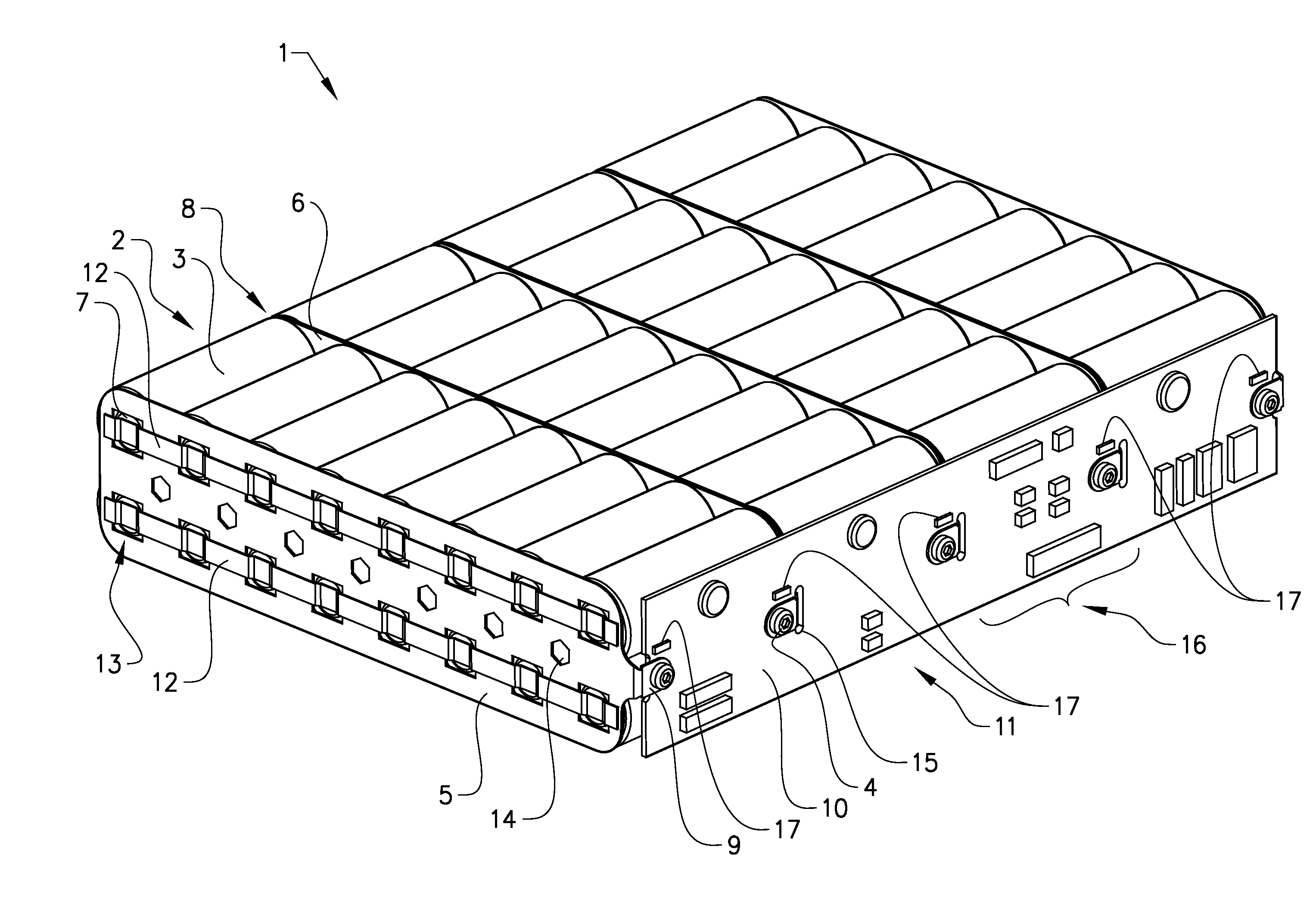
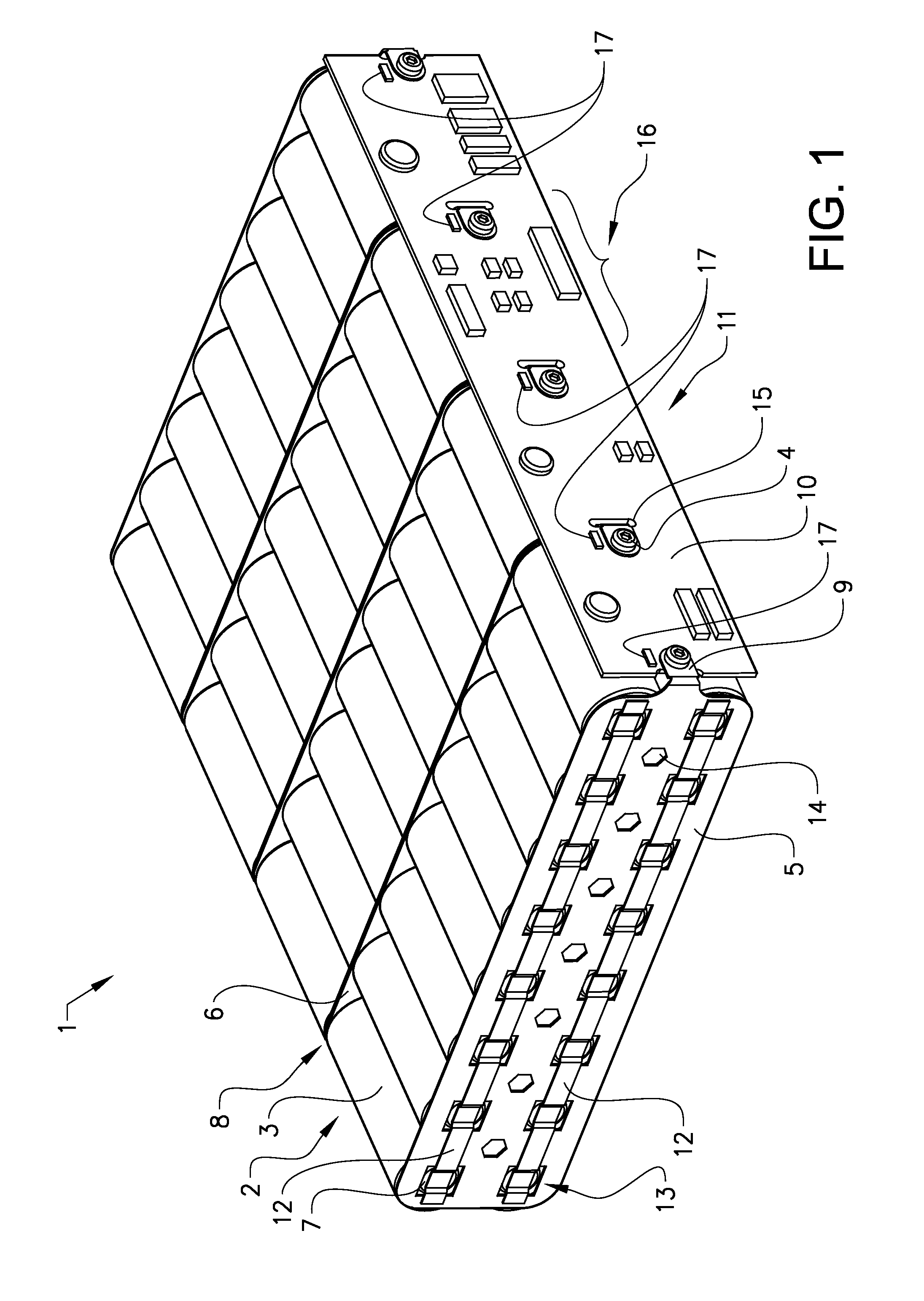
[0018]FIG. 1 shows a first preferred embodiment of a battery assembly 1 according to the invention.

[0019]The battery assembly 1 comprises, in this example, four similar battery blocks 2 of rechargeable battery cells 3 and a printed circuit board (PCB) 10 provided with an electronic circuit 11 (only schematically shown in the figures) configured to monitor and control the battery assembly 1 and to balance each of the cell blocks 2. The PCB is mounted to the battery blocks 2 by mounting means 4 arranged to electrically connect the cell blocks 2 to the PCB 10 and also to mechanically hold the PCB in a fixed position.

[0020]Each battery block 4 comprises a plurality of rechargeable battery cells 3 arranged side by side in one or more rows. The positive electrode terminals 7 of the cell members 2 are fixedly connected to a first metal plate 5 and the negative electrode terminals 8 of the cell members 2 are fixedly connected to a second metal plate 6. The shape of the first metal plate 5 a...


PUM

PropertyMeasurementUnit
currentaaaaaaaaaa
thicknessaaaaaaaaaa
thicknessaaaaaaaaaa

Abstract

Battery assembly comprising a plurality of battery blocks, where each battery block comprises a first metal plate fixedly connected to the positive terminals of a plurality of rechargeable battery cell members and a second metal plate fixedly connected to the negative terminals of the cell members, further comprising a printed circuit board provided with an electronic circuit configured to monitor, control and/or balance said battery blocks, where the metal plates of subsequent battery blocks are fixedly connected to each other such that the battery blocks are electrically configured in series, and where the PCB is mechanically fixed to mounting flanges of the metal plates with mounting means that also provides an electric connection between the metal plates and the PCB. The advantage of the invention is that a self-supporting battery assembly that can be produced in a cost-effective way is provided.

Description

TECHNICAL FIELD[0001]This invention relates to a battery assembly comprising a plurality of battery blocks. In particular, the invention relates to a rechargeable battery assembly for applications requiring a relatively high power, such as driving of vehicles. The invention also relates to a battery system comprising a plurality of battery assemblies.BACKGROUND OF THE INVENTION[0002]Rechargeable batteries of the lithium-ion (Li-ion) or nickel-cadmium (Ni—Cd) type, or similar, have become increasingly interesting as an energy source for driving vehicles (cars, golf-carts, motor-bikes etc.) and other devices, such as boat engines and cleaning machines, as well as for powering e.g. cellular network base stations (together with solar or wind power equipment) in remote areas.[0003]In such applications several battery cells are connected in series and / or parallel in a battery pack or assembly such as to be capable of delivering the required power / current / voltage. Normally, a battery pack ...

Claims


Application Information

Patent Timeline
Patent Type & Authority Applications(United States)
IPC IPC(8): H01M10/48H01M10/04H01M50/20H01M50/213H01M50/284H01M50/502H01M50/581
CPCH01M2/1072Y10T29/49108H01M2/348H01M10/0525H01M10/5016H01M10/5026H01M10/503H01M10/5063H01M10/04H01M10/486H01M2/1077H01M10/482H01M10/5006H01M10/5008H01M10/504H01M10/5083H01M2/206H01M10/625H01M10/615H01M10/637H01M10/653H01M10/6571H01M10/643H01M10/617H01M10/6561Y02E60/10H01M50/502H01M50/581Y02P70/50H01M50/284H01M50/213
Inventor BENGTSSON, HENRIKJONSSON, MAGNUSPETTERSSON, ERIKTORELL, MAGNUSHELGESON, DAVIDLUNDSTROM, DAGANGEBRAND, NIKLAS
Owner ALELION ENERGY SYST AB
Why Eureka
Try Eureka