Energy Recovery Ventilator With Reduced Power Consumption

a ventilator and power consumption technology, applied in ventilation systems, lighting and heating apparatus, heating types, etc., can solve the problem of high energy cost of fresh air delivery, and achieve the effect of reducing the power used by the blower motor

Active Publication Date: 2013-08-29
CARRIER CORP
View PDF27 Cites 15 Cited by
  • Summary
  • Abstract
  • Description
  • Claims
  • Application Information

AI Technical Summary

Benefits of technology

[0004]One embodiment is an air conditioning unit including a passage having a heat exchanger; a blower for blowing air through the passage; a blower motor driving the blower in response to a drive si

Problems solved by technology

However, during heating and cooling off cycles, running the blower for ventilation results in a higher ene

Method used


Image

  • Energy Recovery Ventilator With Reduced Power Consumption
  • Energy Recovery Ventilator With Reduced Power Consumption
  • Energy Recovery Ventilator With Reduced Power Consumption

Examples


Embodiment Construction

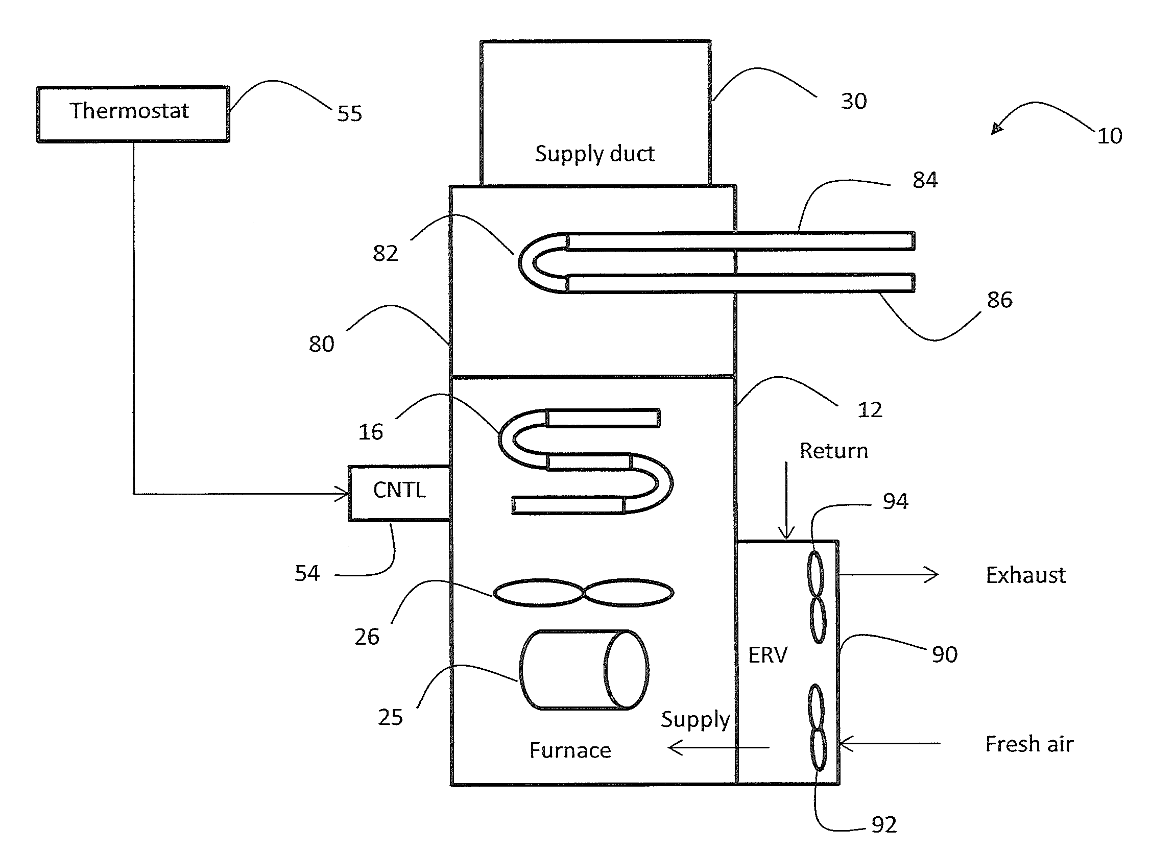
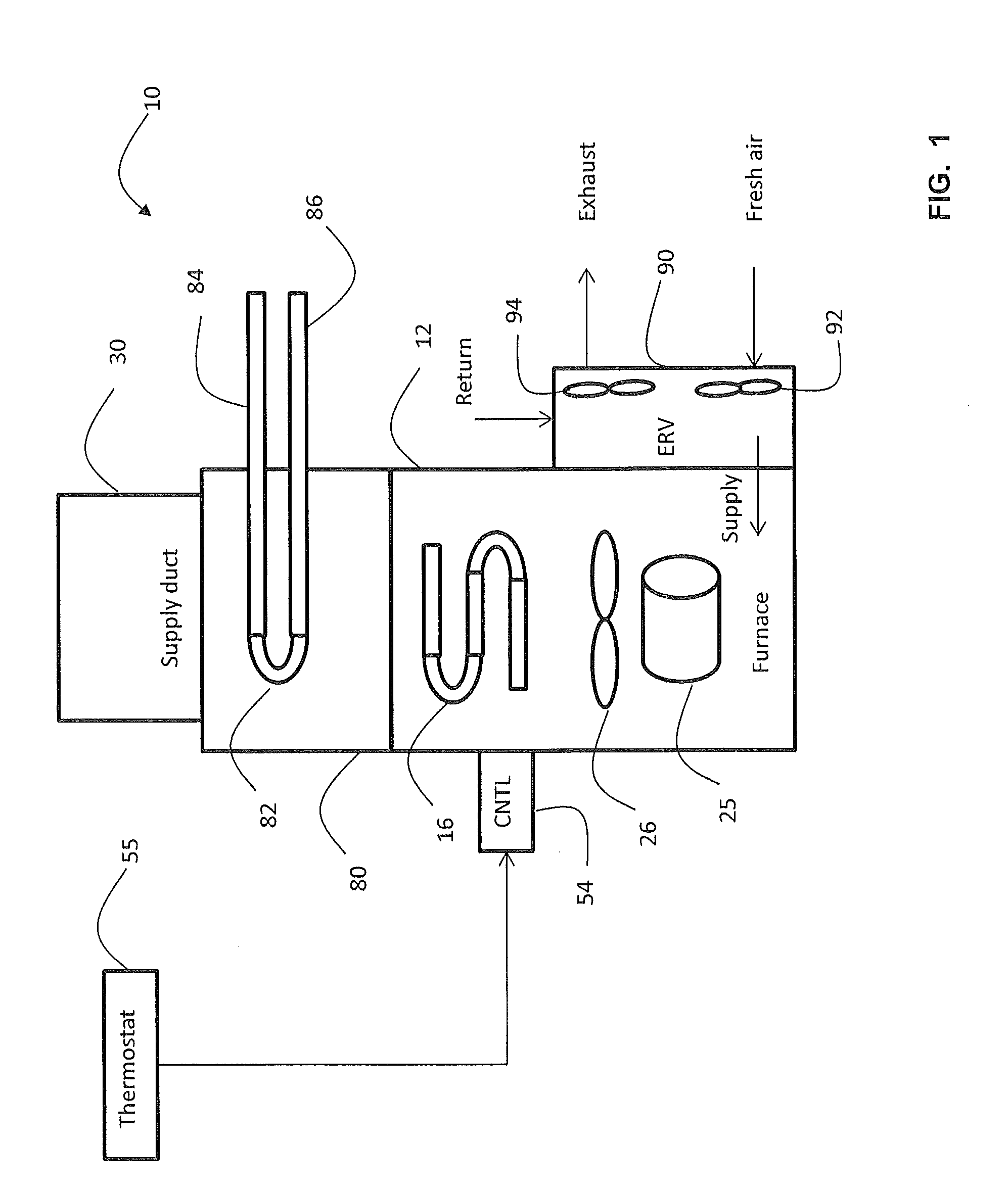
[0009]Referring to FIG. 1, numeral 10 generally designates an air conditioning unit having a furnace, an evaporator coil and an energy recovery ventilator (ERV). The ERV is described herein with reference to a gas furnace, but it is understood that the ERV (and control thereof) may be used with other systems, such as residential air handlers, and embodiments are not limited to a gas fired furnace as shown in FIG. 1. Air conditioning unit, as used herein, is intended to cover a variety of air handling equipment.

[0010]Air conditioning unit 10 includes a cabinet 12 housing therein furnace having a circulating air blower 26 driven by a blower motor 25. In heating mode, a heat exchanger 16 heats air circulated by air blower 26, which is supplied to a supply duct 30. A burner assembly, igniter, gas source, etc. are not shown for ease of illustration. An evaporator coil 82 is located in housing 80 on top of cabinet 12 and is the evaporator of a cooling unit. The evaporator coil 82 has an i...


PUM


Abstract

An air conditioning unit includes a passage having a heat exchanger; a blower for blowing air through the passage; a blower motor driving the blower in response to a drive signal; an energy recovery ventilator (ERV), the blower drawing outside air from the ERV; and a controller for adjusting the drive signal in a ventilation mode to reduce power used by the blower motor.

Description

CROSS-REFERENCE TO RELATED APPLICATIONS[0001]This application claims the benefit of U.S. provisional patent application Ser. No. 61 / 604,559 filed Feb. 29, 2012, the entire contents of which are incorporated herein by reference.BACKGROUND OF THE INVENTION[0002]The subject matter disclosed herein generally relates to energy recovery ventilators, and in particular to a method and system for controlling an energy recovery ventilator to reduce power consumption and provide energy savings.[0003]Energy recovery ventilators (ERVs) are used to provide fresh air circulation to a location. Fresh air circulation is particularly helpful in homes that are well sealed and highly insulated. Existing residential ERV's often require the furnace or air handler blower to run during ventilation mode because the fresh air delivery is done through the main air duct system for the home. During heating and cooling cycles there is no additional cost for ventilation because the blower runs during the heating ...

Claims


Application Information

Patent Timeline
IPC IPC(8): F24F11/00
CPCF24F11/0079Y02B30/746F24F11/0001F24F11/77F24F12/001
Inventor HEBERER, DWIGHT H.DEMPSEY, DANIEL J.THOMPSON, KEVIN D.ADAMS, ERIC W.KUFFNER, KENT
Owner CARRIER CORP
Why Eureka
Try Eureka