Laser Sight Firing Device Mountable To An Air Gun

Inactive Publication Date: 2013-09-05
TSAI CHING LI
View PDF5 Cites 1 Cited by
  • Summary
  • Abstract
  • Description
  • Claims
  • Application Information

AI Technical Summary

Benefits of technology

[0013]Since the laser sight firing device is configured as an integral unit that has a simple st

Problems solved by technology

(1) Complicated structure: the conventional simulated gun 1 includes a laser sight firing device having a large number of components that are dispersed therein. Such a laser sight firing device cannot be mounted removably to an air gun to constitute the conventional simulated gun 1, thereby increasing the molding cost of the simulated gun 1.
(2) Inconvenient assembl

Method used


Image

  • Laser Sight Firing Device Mountable To An Air Gun
  • Laser Sight Firing Device Mountable To An Air Gun
  • Laser Sight Firing Device Mountable To An Air Gun

Examples


Embodiment Construction

[0032]Before the present invention is described in greater detail in connection with the preferred embodiments, it should be noted that similar elements and structures are designated by like reference numerals throughout the entire disclosure.

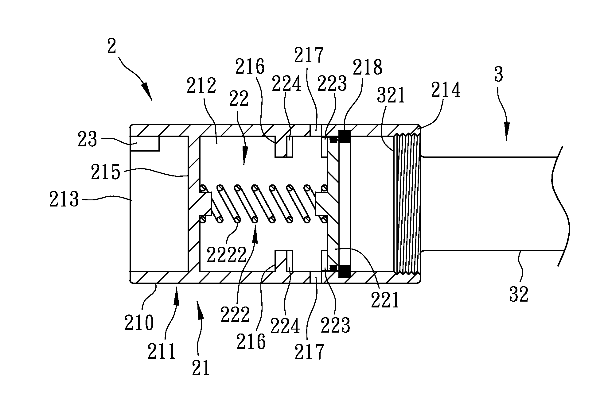
[0033]Referring to FIGS. 3 and 4, the first preferred embodiment of a laser sight firing device 2 according to this invention is disposed on an air gun 3 for simulating a real shooting. In this embodiment, the air gun 3 is configured as a rifle. The air gun 3 includes a main body 31, a gun barrel 32 connected to the main body 31, and a trigger 33 connected to the main body 31 and operable for driving emission of a high-pressure air current from the main body 31 and through the gun barrel 32. The gun barrel 32 is formed with a muzzle 321 at an end thereof distal from the main body 31.

[0034]With further reference to FIG. 5, the laser sight firing device 2 includes a firing unit 21 disposed on the gun barrel 32, a sensing unit 22 disposed in the f...


PUM


Abstract

A laser sight firing device is usable with an air gun, and includes a firing unit disposed on the gun barrel, a sensing unit, and a light emitter disposed on the firing unit. The firing unit includes a tubular member, and a position-limiting member extending from the tubular member. The tubular member has a tube wall formed with an air discharge hole and defining a passage. The sensing unit includes a piston disposed in the passage, a return mechanism disposed between the piston and the position-limiting member, a first chip module disposed on the piston, and a second chip module disposed fixedly in the passage. When air current flows from the air gun, the first chip module comes into contact with the second chip module to activate the light emitter to emit light.

Description

CROSS-REFERENCE TO RELATED APPLICATION[0001]This application claims priority of Taiwanese Application No. 101107312, filed on Mar. 5, 2012.BACKGROUND OF THE INVENTION[0002]1. Field of the Invention[0003]This invention relates to a laser sight firing device, and more particularly to a laser sight firing device that can be mounted to an air gun to form a simulated gun assembly that is operable to simulate a real shooting.[0004]2. Description of the Related Art[0005]Referring to FIG. 1, a simulated gun 1 disclosed in Taiwanese Utility Model Patent No. 320281 includes main body 11 having a compartment 111, a sleeve tube unit 12 disposed in the compartment 111, and a trigger unit 13 exposed partially from the compartment 111. The main body 11 further has a microswitch 112 disposed in the compartment 111, a gun barrel 113 extending from an end of the main body 11, and a light emitter 114 disposed in the gun barrel 113 and activatable by the microswitch 112. The sleeve tube unit 12 include...

Claims


Application Information

Patent Timeline
IPC IPC(8): F41G1/35
CPCF41G1/35F41A33/02
Inventor TSAI, CHING-LI
Owner TSAI CHING LI
Why Eureka
Try Eureka