Oil-cooled oil tank

a technology of oil tanks and oil tanks, applied in medical science, dental surgery, fire rescue, etc., can solve the problems of limited durability of fire blankets and fire-resistant coatings, and achieve the effects of reducing weight, improving fire resistance, and limited durability

Inactive Publication Date: 2013-09-05
PARKER HANNIFIN CORP
View PDF5 Cites 3 Cited by
  • Summary
  • Abstract
  • Description
  • Claims
  • Application Information

AI Technical Summary

Benefits of technology

[0005]The present invention provides an aluminum or other lightweight tank that provides significant weight savings over the standard stainless steel oil tanks. Besides adding weight, fire blankets and fire-resistant coatings may have limited durability. To provide the same or better fire resistance, the tank provided by the present invention includes means for spraying oil against the inside walls of the tank as the oil enters the tank. This oil forms a sheet that flows down the walls of the tank to minimize the temperature of the walls of the tank. Thus the invention allows the use of an aluminum tank without the need for a blanket of heat-resistant insulation or a fire-resistant coating. In addition, spraying the oil against the side walls of the tank may improve air-oil separation.
[0010]The present invention also provides a method of minimizing the temperature of a container for a liquid. The method includes the step of directing a stream of liquid against an upper portion of an inside surface of the container to form a sheet of liquid on the inside surface.

Problems solved by technology

Besides adding weight, fire blankets and fire-resistant coatings may have limited durability.

Method used


Image

  • Oil-cooled oil tank
  • Oil-cooled oil tank
  • Oil-cooled oil tank

Examples


Embodiment Construction

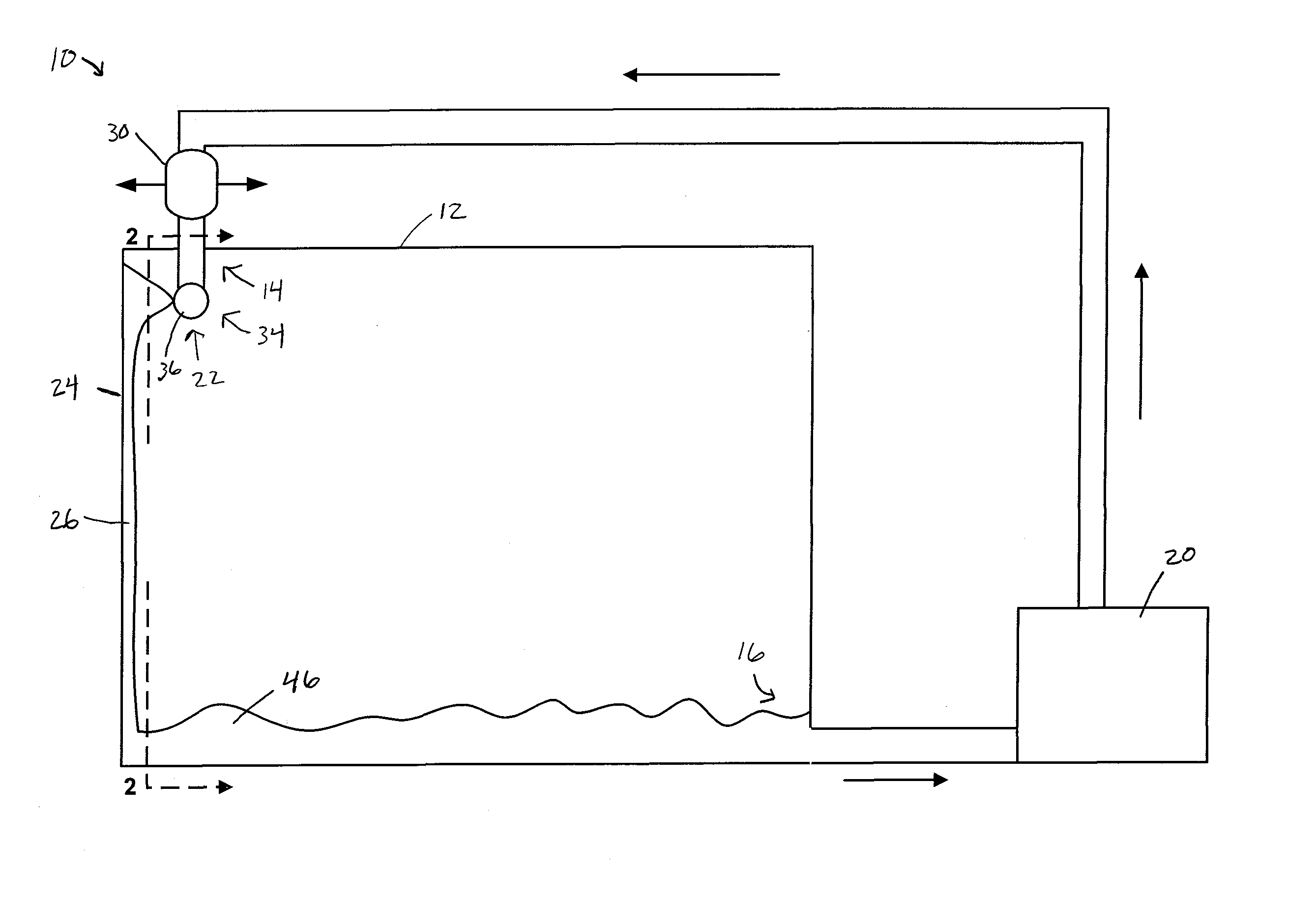
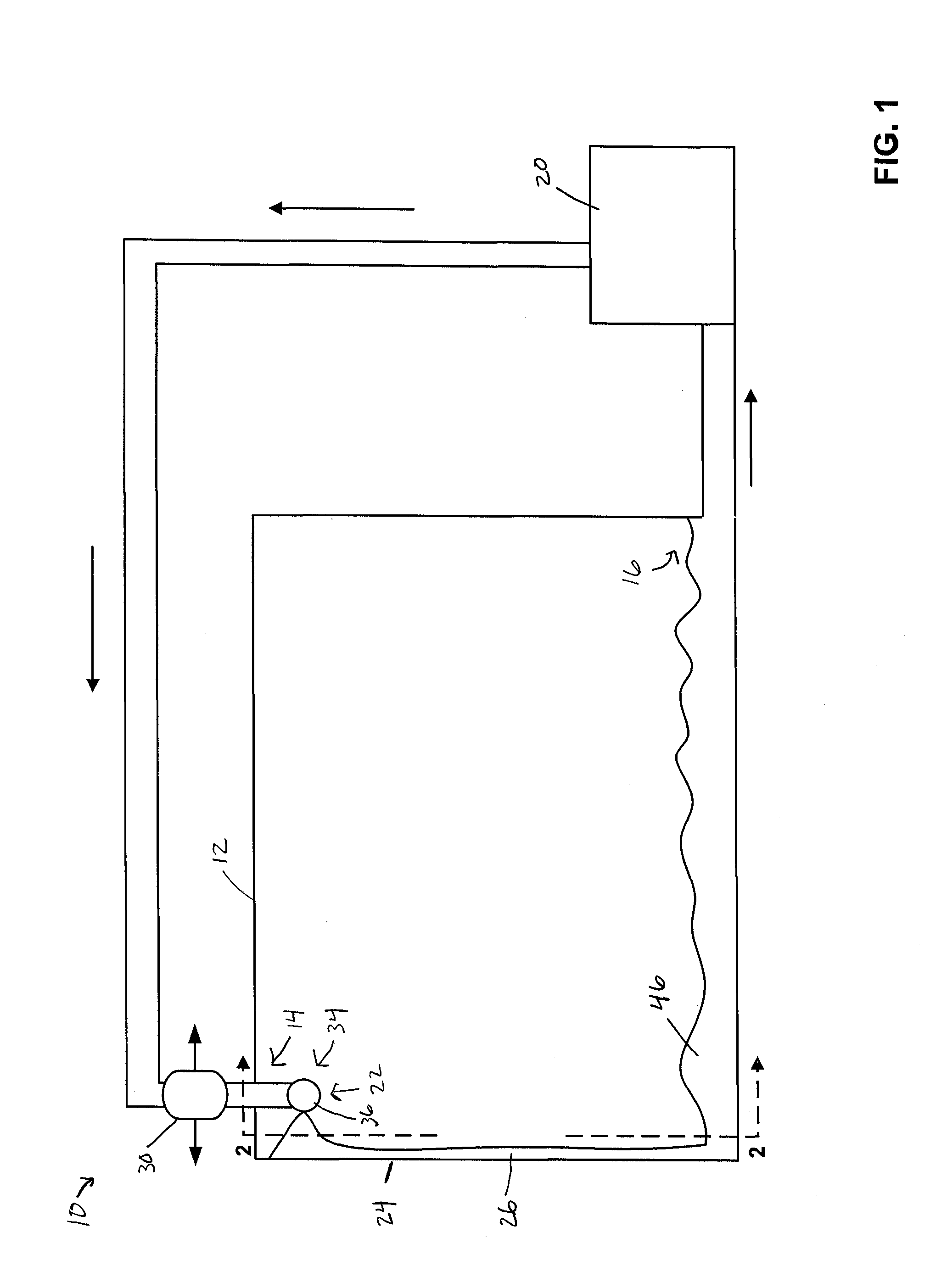
[0016]Referring now to the drawings, and initially FIG. 1, the present invention provides an improved tank assembly 10 for containing liquid for use on an aircraft. The tank assembly 10, includes a lightweight container 12 (also referred to as a tank) for liquid, such as oil, that is provided with features that make the container 12 more resistant to damage from heat, such as the heat of a fire. The invention is not limited to containers for oil, however. While oil is an exemplary liquid for use in the tank, other liquids can be used with the principles of the invention. So while the invention will be described with reference to an oil tank, references to oil include alternative liquids, such as hydraulic liquid, liquid fuel, water, etc.

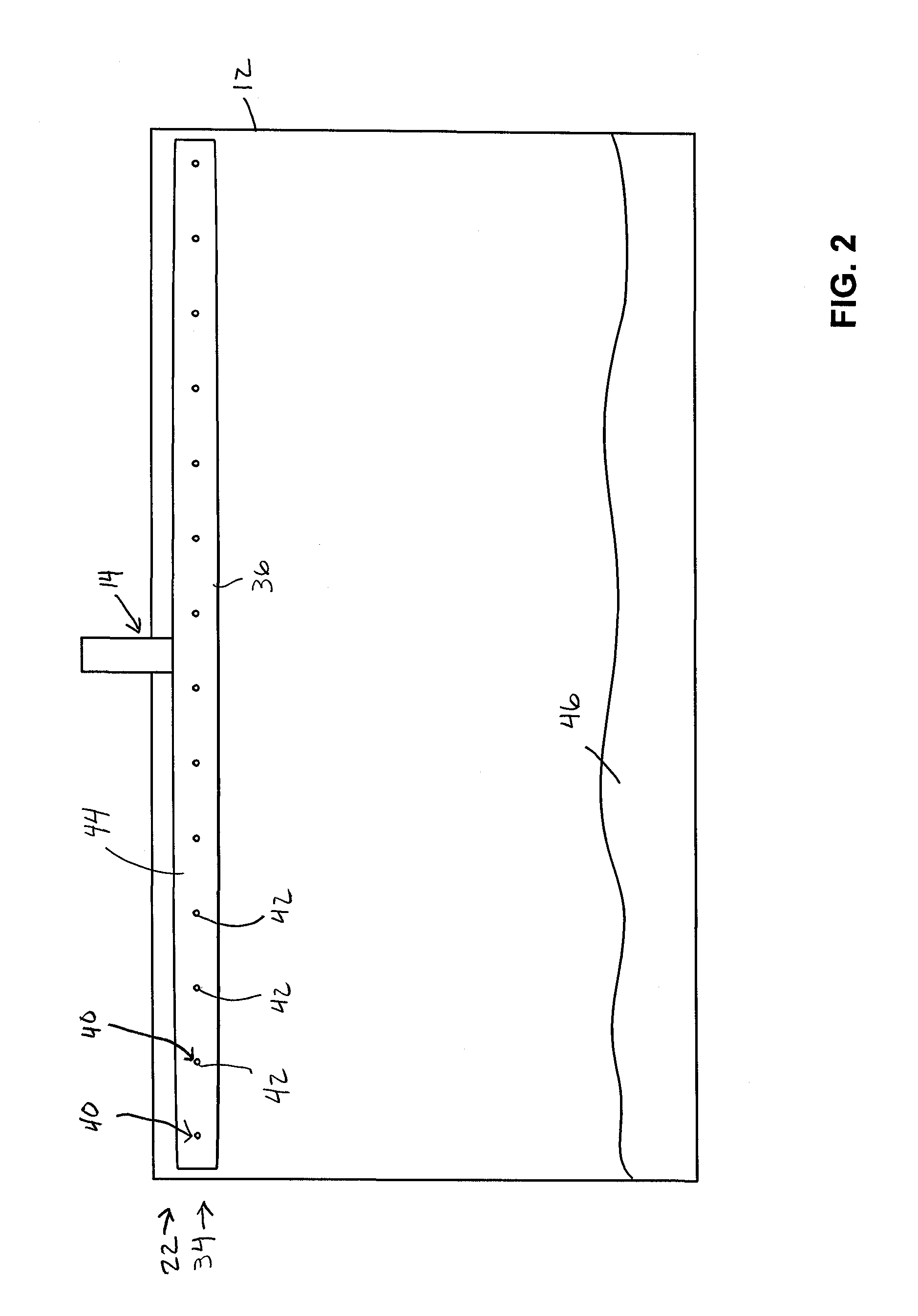
[0017]The container 12 includes an inlet 14, and an outlet 16. The tank assembly 10 further includes a pump 20 fluidly coupled to at least one of the inlet 14 and the outlet 16 to pump oil into or out of the container 12. The container 12 preferably ...


PUM


Abstract

A tank assembly for containing liquid with increased heat resistance includes a lightweight container for liquid having an inlet and an outlet, and a spray assembly. The spray assembly includes means for spraying a liquid, also called a spray device, inside the container that is fluidly connected to the inlet. The spray device has an orifice located so as to direct liquid received from the inlet against an inside surface of the container walls. The liquid forms a sheet that flows down the walls of the container to a pool of liquid to reduce the temperature of the walls of the container above the pool.

Description

RELATED APPLICATIONS[0001]This application claims the benefit of U.S. Provisional Application No. 61 / 605,963 filed Mar. 2, 2012, which is hereby incorporated herein by reference.FIELD OF THE INVENTION[0002]The present invention is directed to an oil tank for an aircraft, and more particularly to a system and method for increasing the fire resistance of such a oil tank.BACKGROUND OF THE INVENTION[0003]An aircraft includes a lubrication system that circulates oil to lubricate the engine. The oil circulation system includes a tank that acts as the reservoir for the lubricating oil. Aircraft regulating agencies require most commercial aircraft to have oil tanks that can withstand direct impingement of flames during an engine fire for a specified time period without leaking any oil.[0004]Such tanks often are made of stainless steel. Typical added fire-protection systems employ a blanket of fire-resistant insulation (commonly referred to as a fire blanket) wrapped around the tank or a fir...

Claims


Application Information

Patent Timeline
Patent Type & Authority Applications(United States)
IPC IPC(8): A62C2/00
CPCA62C2/00A62C3/065
Inventor SCOTT, RICHARD E.
Owner PARKER HANNIFIN CORP
Why Eureka
Try Eureka