
Spectral band-pass filter having high selectivity and controlled polarization

a filter and band-pass technology, applied in the direction of optical radiation measurement, instruments, applications, etc., can solve the problems of brittleness of hardware components, rapid development of thickness-related technology difficulties, and destruction of structur

Active Publication Date: 2013-09-05
OFFICE NAT DETUD & DE RECH AEROSPATIALES
View PDF0 Cites 19 Cited by
  • Summary
  • Abstract
  • Description
  • Claims
  • Application Information

AI Technical Summary

Benefits of technology

The optronic detection system described in this patent includes a polarizer that helps to polarize an incident wave in a specific direction. This can be useful in improving the performance of the detection system by better controlling the direction of the incident wave.

Problems solved by technology

However, once they involve a large number of thin layers, these hardware components exhibit brittleness as soon as they are subjected to cycles of temperature variations, for example when they are disposed in a cryostat, especially for applications in the infrared.
Indeed, these cycles lead to destruction of the structure owing to the thermal expansion coefficients which, differing from one material to another and therefore from one layer to another, induce stresses.
Furthermore, a filter operating in the infrared will require thicker layers than a filter operating in the visible, and thickness-related technological difficulties will arise very rapidly, said difficulties being made worse during the production of arrays of filters, wherein it will be necessary to vary the thicknesses from one filter to another.
Hardware components based on the technology of the stacking of thin layers do not allow polarization-dependent selectivity.

Method used


Image

  • Spectral band-pass filter having high selectivity and controlled polarization
  • Spectral band-pass filter having high selectivity and controlled polarization
  • Spectral band-pass filter having high selectivity and controlled polarization

Examples


Embodiment Construction

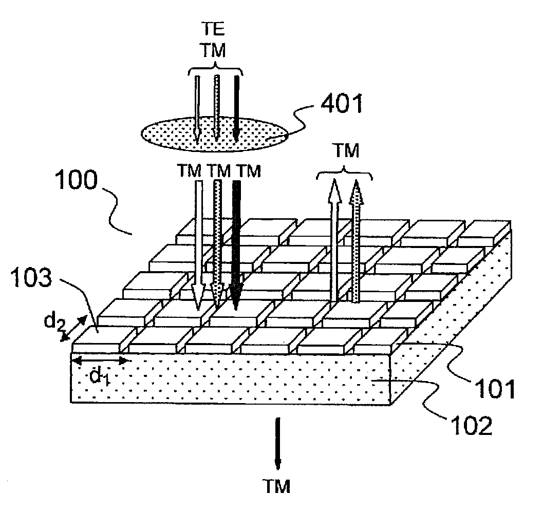
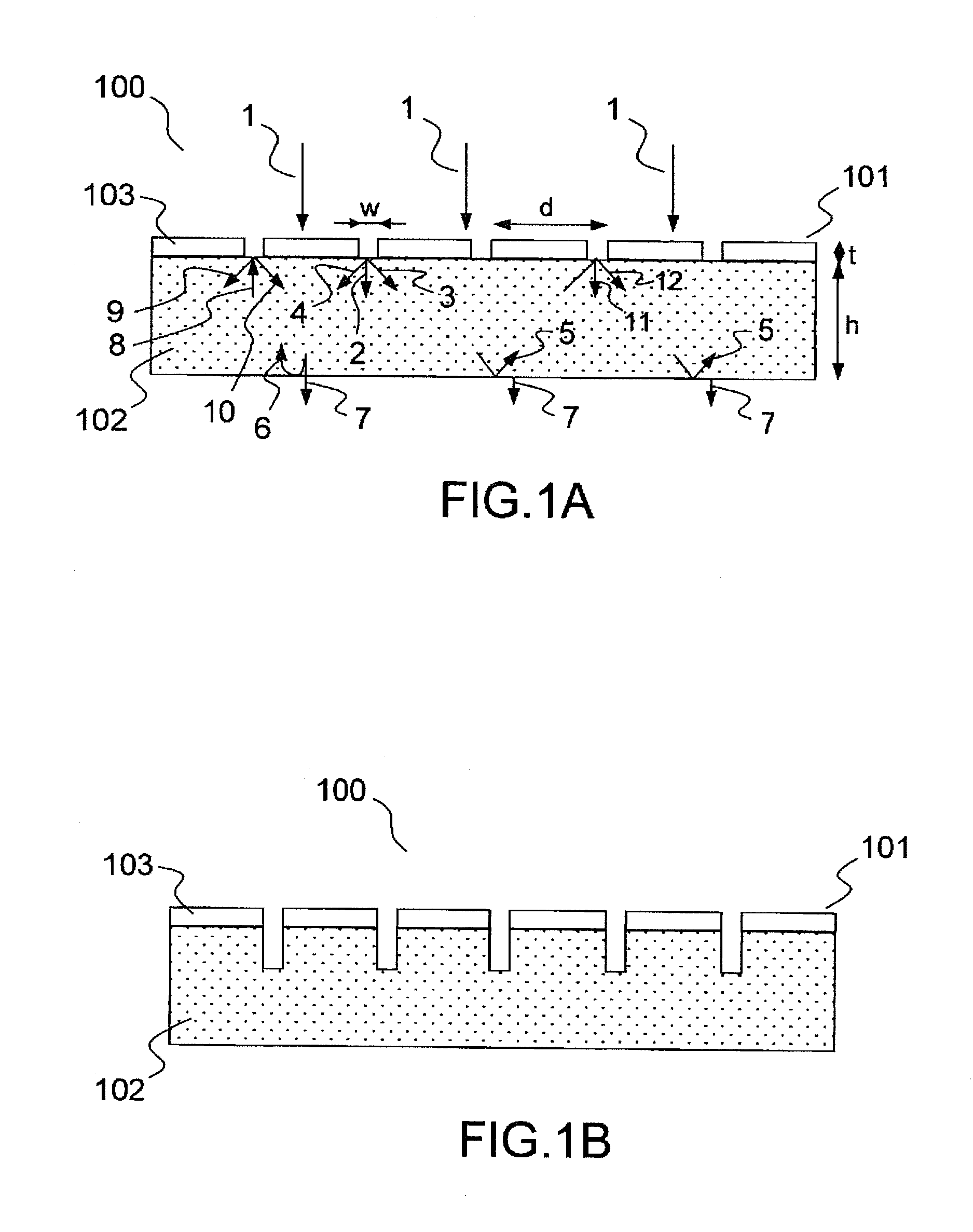
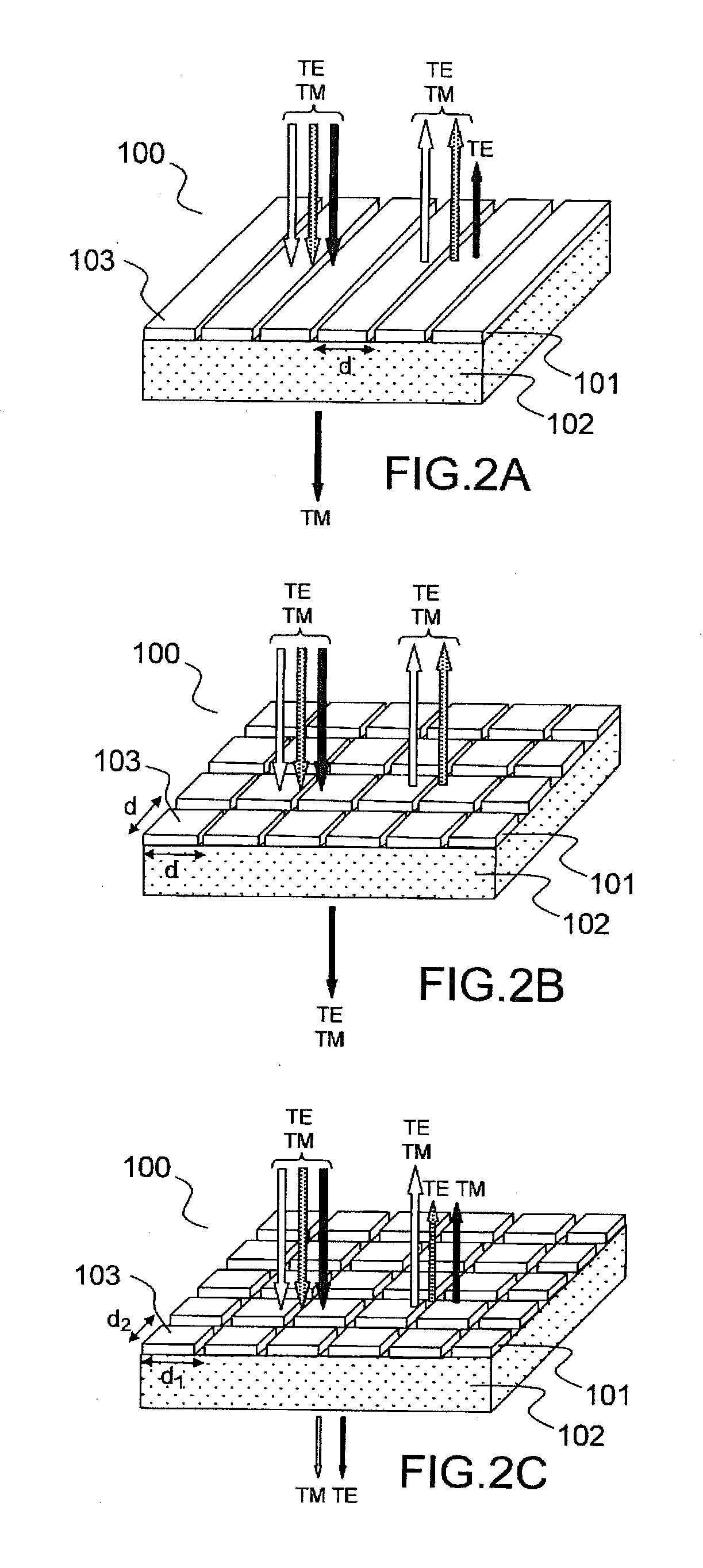
[0038]FIG. 1A illustrates by a diagram the principle of an exemplary bandpass filter 100 according to the invention (sectional view) while FIGS. 2A to 2C represent perspective views of various exemplary embodiments. The filter 100 comprises a thin layer 102 of dielectric material on which is deposited a metallic film 101 perforated periodically, in one or more directions, by a sub-wavelength pattern 103, the whole being suspended, that is to say not deposited on a substrate except in zones where the spectral filtering functionality is not sought. For example, the metallic film and dielectric layer assembly is suspended on the rim of an orifice formed in a substrate (not represented in FIG. 1A). In use, the structure is therefore immersed in the ambient medium (vacuum or arbitrary fluid). The layer 102 is made of dielectric material transparent in the spectral band that one seeks to transmit, for example silicon nitride or silicon carbide. Other materials can be used such as for exam...


PUM


Abstract

According to one aspect, the invention relates a spectral band-pass filter, which is optimized for the transmission of an incident wave at at least a first given central wavelength λ0, and which includes: a metal grating having a thickness (t) greater than approximately λ0 / 50 and including at least a first set of substantially identical, parallel slots having a width (W) less than around λ0 / 10, and being spaced apart periodically or quasi-periodically according to a first period that is less than said first central el wavelength, a layer of dielectric material having a thickness (h) and a given refractive index (ng), which is coupled to the metal grating to form a waveguide for the waves diffracted by the grating, said first period of the grating being designed such that only orders 0 and ±1 of a wave having normal incidence and a wavelength λ0 are diffracted in the layer of dielectric material, the assembly of the dielectric layer and grating being suspended, during use, in a fluid having a refractive index of close to 1.

Description

PRIOR ARTTechnical Field of the Invention[0001]The present invention relates to a spectral filter having high selectivity and controlled polarization, especially for the production of filters in the infrared.Prior Art[0002]A known conventional technique for carrying out a bandpass filtering function consists in stacking thin layers, taking care to choose the number, the thicknesses of the layers and the nature of the materials as a function of the template desired for the filter. Patent application WO2008122431 describes for example such a filter, termed an interferential filter. However, once they involve a large number of thin layers, these hardware components exhibit brittleness as soon as they are subjected to cycles of temperature variations, for example when they are disposed in a cryostat, especially for applications in the infrared. Indeed, these cycles lead to destruction of the structure owing to the thermal expansion coefficients which, differing from one material to anot...

Claims


Application Information

Patent Timeline
Patent Type & Authority Applications(United States)
IPC IPC(8): G02B5/20G01J3/28
CPCB82Y20/00G02B5/1809G02B5/201G02B5/203G02B2207/101G01J3/28G02B5/204
Inventor VINCENT, GREGORYHAIDAR, RIADCOLLIN, STEPHANEPELOUARD, JEAN-LUC
Owner OFFICE NAT DETUD & DE RECH AEROSPATIALES
Learn More