
Method and apparatus for solid-state microbattery photolithographic manufacture, singulation and passivation

a micro-battery and photolithographic technology, applied in the direction of nanobatteries, cell components, sustainable manufacturing/processing, etc., can solve the problems of not including the power supply with the device, the power supply is quite heavy and/or large, and the device is fabricated from potentially toxic materials. , to achieve the effect of reducing the number of steps

Inactive Publication Date: 2013-09-05
CYMBET CORP
View PDF3 Cites 12 Cited by
  • Summary
  • Abstract
  • Description
  • Claims
  • Application Information

AI Technical Summary

Benefits of technology

The patent describes a new way to make thin film lithium batteries using photolithographic methods. This process is more efficient and economical than previous methods, and it uses less complicated equipment. No extra protective layers are needed, which makes the process easier. Overall, this patent provides a more streamlined way to make these batteries.

Problems solved by technology

One drawback to portable devices is the need to include the power supply with the device.
Sufficient battery capacity can result in a power supply that is quite heavy and / or large compared to the rest of the device.
Another drawback of conventional batteries is the fact that some are fabricated from potentially toxic materials that may leak and be subject to governmental regulation.
This configuration requires providing air access to substantially the entire cathode surface, limiting the ability to densely stack layers for higher electrical capacity (i.e., amp-hours).

Method used


Image

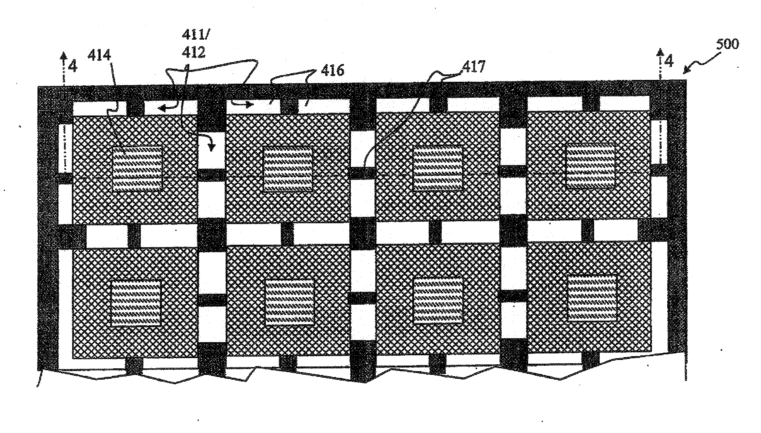
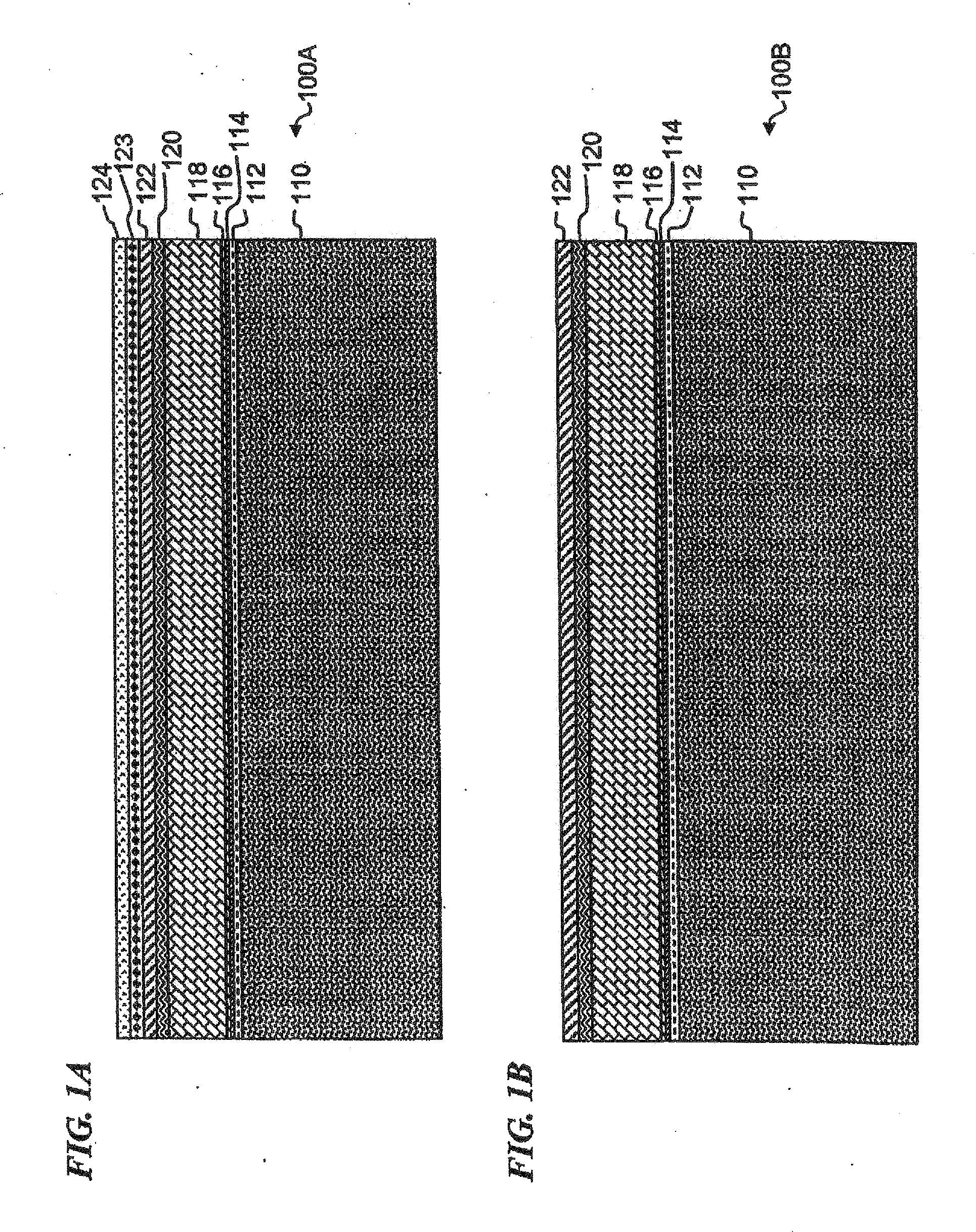
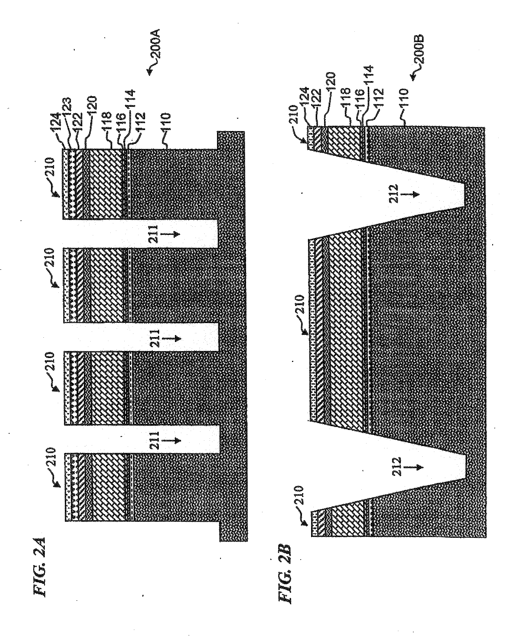
  • Method and apparatus for solid-state microbattery photolithographic manufacture, singulation and passivation
  • Method and apparatus for solid-state microbattery photolithographic manufacture, singulation and passivation
  • Method and apparatus for solid-state microbattery photolithographic manufacture, singulation and passivation

Examples


Embodiment Construction

[0035]In the following detailed description of the preferred embodiments, reference is made to the accompanying drawings that form a part hereof, and in which are shown by way of illustration specific embodiments in which the invention may be practiced. It is understood that other embodiments may be utilized and structural changes may be made without departing from the scope of the present invention.

[0036]The leading digit(s) of reference numbers appearing in the Figures generally correspond to the Figure number in which that component is first introduced, such that the same reference number is used throughout to refer to an identical component which appears in multiple Figures. Signals (such as, for example, fluid pressures, fluid flows, or electrical signals that represent such pressures or flows), pipes, tubing or conduits that carry the fluids, wires or other conductors that carry the electrical signals, and connections may be referred to by the same reference number or label, a...


PUM

PropertyMeasurementUnit
thicknessaaaaaaaaaa
thicknessesaaaaaaaaaa

Abstract

A method for producing a thin film lithium battery is provided, comprising applying a cathode current collector, a cathode material, an anode current collector, and an electrolyte layer separating the cathode material from the anode current collector to a substrate, wherein at least one of the layers contains lithiated compounds that is patterned at least in part by a photolithography operation comprising removal of a photoresist material from the layer containing lithiated compounds by a process including a wet chemical treatment. Additionally, a method and apparatus for making lithium batteries by providing a first sheet that includes a substrate having a cathode material, an anode material, and a LiPON barrier / electrolyte layer separating the cathode material from the anode material; and removing a subset of first material to separate a plurality of cells from the first sheet. In some embodiments, the method further includes depositing second material on the sheet to cover the plurality of cells; and removing a subset of second material to separate a plurality of cells from the first sheet.

Description

[0001]This application claims the benefit of U.S. Provisional Application Ser. No. 60 / 807,713, filed Jul. 18, 2006, entitled “METHOD AND APPARATUS FOR SOLID-STATE MICROBATTERY PHOTOLITHOGRAPHIC SINGULATION AND PASSIVATION FROM A SUBSTRATE” which application is incorporated herein by reference in its entirety.FIELD OF THE INVENTION[0002]This invention relates to the field of solid-state energy-storage devices, and more specifically to a method and apparatus for making solid-state batteries and singulating the devices (mostly separating from each other while optionally leaving small connections to the surrounding waste substrate, or completely separating the devices) and creating passivation around the battery devices, e.g., lithium battery devices with a LiPON electrolyte, wherein the battery devices also optionally include LiPON as a passivation and protective barrier, and the resulting cell(s), device(s) and / or battery(s).BACKGROUND OF THE INVENTION[0003]Electronics have been incor...

Claims


Application Information

Patent Timeline
Patent Type & Authority Applications(United States)
IPC IPC(8): H01M10/04H01M4/52H01M10/36
CPCH01M4/525H01M6/40H01M10/0436H01M10/052H01M10/056H01M10/04H01M10/0585H01M2010/0495H01M2300/0094Y02E60/122H01M10/0562Y02E60/10Y02P70/50H01M4/1391H01M2300/0068H01M10/045
Inventor WALLACE, MARK A.KLAASSEN, JODY J.SATHER, JEFFREY J.SHAKESPEARE, STUART K.
Owner CYMBET CORP
Learn More