
Electronic Apparatus and Power Supply Control System

Inactive Publication Date: 2013-09-05
FUNAI ELECTRIC CO LTD
View PDF9 Cites 7 Cited by
  • Summary
  • Abstract
  • Description
  • Claims
  • Application Information

AI Technical Summary

Benefits of technology

The invention provides electronic devices and power supply control systems that can reduce power consumption when power is supplied to functional blocks.

Problems solved by technology

Thus, it is difficult to reduce power consumption.

Method used


Image

  • Electronic Apparatus and Power Supply Control System
  • Electronic Apparatus and Power Supply Control System
  • Electronic Apparatus and Power Supply Control System

Examples


first embodiment

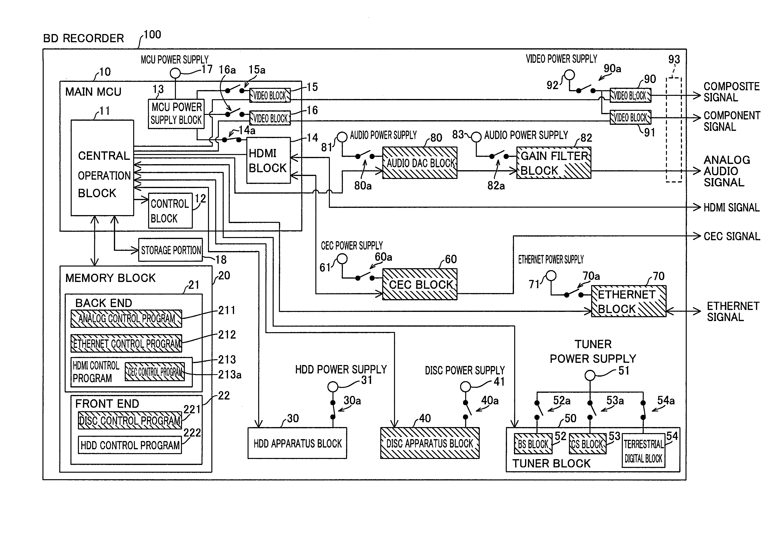
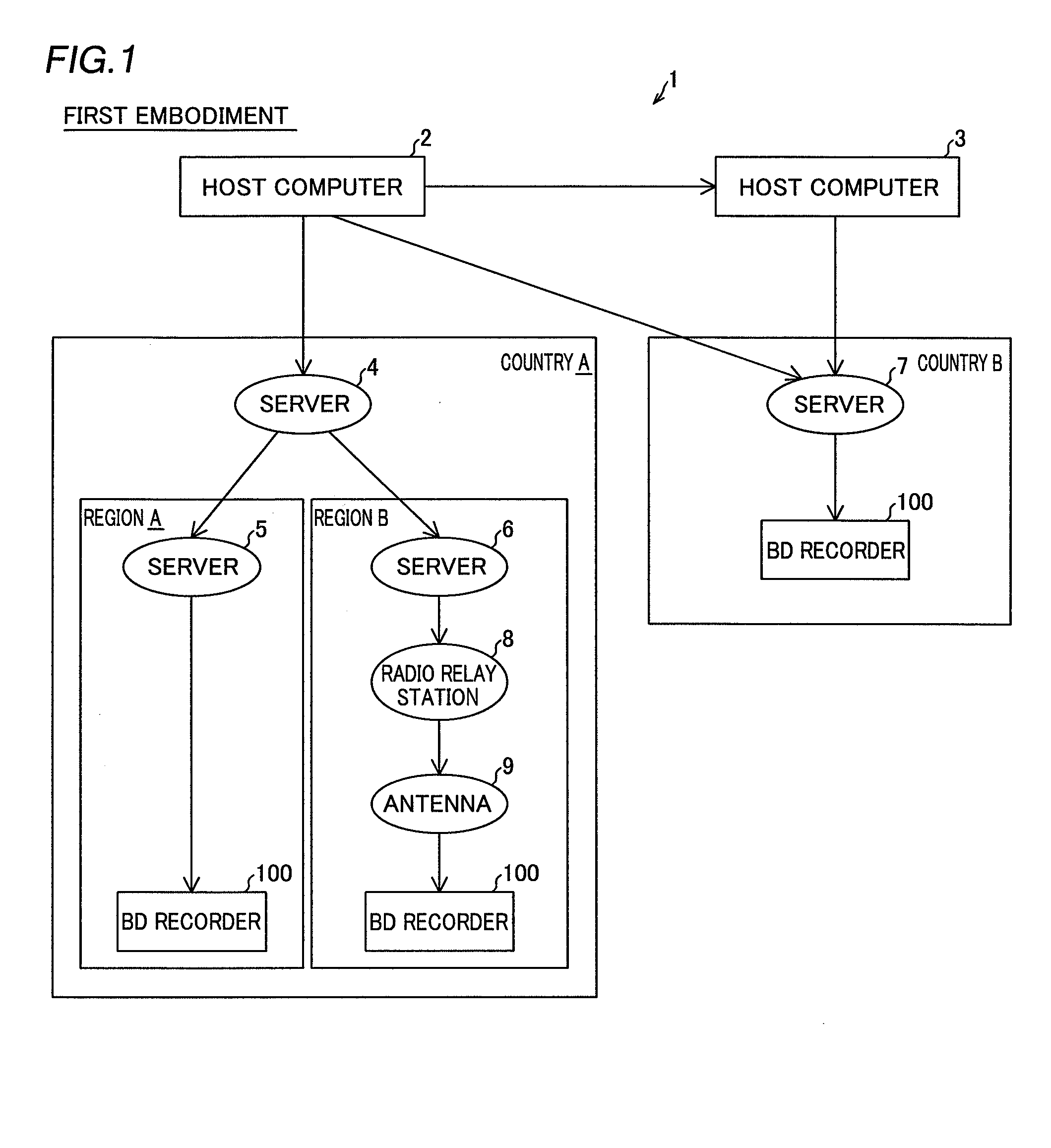
[0042]First, the structure of a power supply control system 1 according to a first embodiment of the present invention is described with reference to FIG. 1.

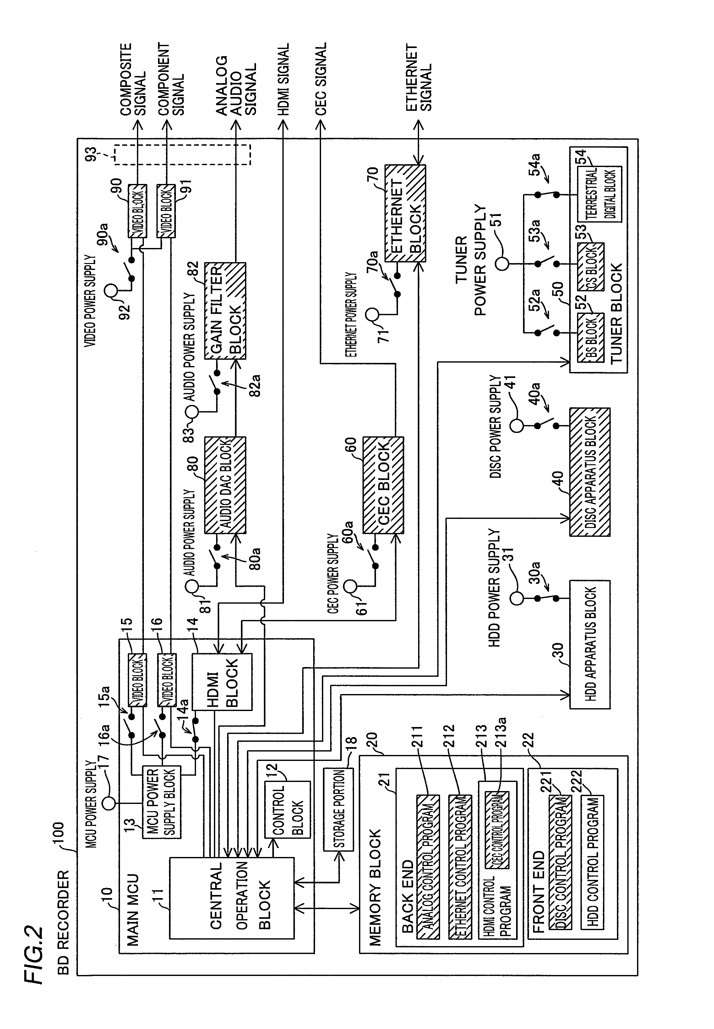
[0043]The power supply control system 1 includes host computers 2 and 3, servers 4, 5, 6, and 7, a radio relay station 8, an antenna 9, and a plurality of BD (Blu-ray Disc) recorders 100, as shown in FIG. 1. The BD recorders 100 are examples of the “electronic apparatus” in the present invention.

[0044]The host computer 2 is configured to be connectable to the host computer 3, the server 4 in a country A, and the server 7 in a country B through a network. The host computer 3 is configured to be connectable to the server 7 in the country B through the network. The host computers 2 and 3 are configured to be capable of receiving use tendency information described later from the BD recorders 100 through the network. Furthermore, the host computers 2 and 3 are configured to be capable of analyzing the use tendency information receive...

second embodiment

[0099]An electronic apparatus management system 101 according to a second embodiment of the present invention is now described with reference to FIGS. 5 to 10. A BD recorder 100 of the electronic apparatus management system 101 according to the second embodiment has the following functions in addition to the functions of the BD recorder 100 according to the first embodiment.

[0100]First, the structure of the electronic apparatus management system 101 according to the second embodiment of the present invention is described with reference to FIG. 5.

[0101]The electronic apparatus management system 101 includes a server 102, the BD (Blu-ray Disc) recorder 100, and a TV (television set) 200, as shown in FIG. 5. The BD recorder 100 is connected to the server 102 through the Internet 103. The BD recorder 100 is an example of the “electronic apparatus” in the present invention, and the TV 200 is an example of the “display device” in the present invention.

[0102]The server 102 is configured to...


PUM


Abstract

This electronic apparatus includes a plurality of functional blocks, a storage portion storing and accumulating use states of the plurality of functional blocks, and a control portion. The control portion is configured to perform control of disconnecting power supplied to a functional block whose usage rate is not more than a prescribed usage rate, tending to be disused, of the plurality of functional blocks in a state where power is supplied to at least one functional block.

Description

BACKGROUND OF THE INVENTION[0001]1. Field of the Invention[0002]The present invention relates to an electronic apparatus and a power supply control system, and more particularly, it relates to an electronic apparatus and a power supply control system each including a plurality of functional blocks.[0003]2. Description of the Background Art[0004]An electronic apparatus including a plurality of functional blocks is known in general, as disclosed in Japanese Patent Laying-Open No. 2011-065494, for example.[0005]The aforementioned Japanese Patent Laying-Open No. 2011-065494 discloses a multi-function apparatus (electronic apparatus) including a copy function, a facsimile function, a printer function, a scanner function (plurality of functional blocks), and a CPU (control portion) controlling power supplied in response to an operating mode such as a normal mode or power-saving mode. In this multi-function apparatus, the CPU is configured to perform control of shifting to the power-saving...

Claims


Application Information

Patent Timeline
IPC IPC(8): G06F1/32
CPCG06F1/3234Y02B60/1282G06F1/3287G06F1/3206Y02D10/00
Inventor MATSUMURA, AKIFUMIYAMASHITA, YUDAI
Owner FUNAI ELECTRIC CO LTD
Learn More