Measuring instrument

a technology of measuring instruments and push buttons, applied in the field of measuring instruments, can solve the problems of difficult to increase the number of mechanical switches, users are forced to perform complicated operations, and various problems, and achieve the effects of reducing the number of components, reducing the thickness, and eliminating mechanical push buttons

Active Publication Date: 2013-09-12
MITUTOYO CORP
View PDF9 Cites 9 Cited by
  • Summary
  • Abstract
  • Description
  • Claims
  • Application Information

AI Technical Summary

Benefits of technology

[0087](1) It becomes possible to eliminate any mechanical push buttons by adopting the touch panel display unit 130. As a result, it is possible to obtain advantageous effects including reducing the thickness, reducing the number of components, and reducing the weight. For example, there is no need to secure the space for the travel of push buttons, and thus making it possible to reduce the thickness of the housing unit 110 by an amount equivalent to the travel of push buttons. As a small tool that is used in a hand-held state, the reduction in the thickness, the size, and / or the weight directly leads to the improvement in the sense of use.
[0088](2) Since the mechanical push buttons are eliminated by adopting the touch panel display unit 130, it is possible to increase the airtight property. That is, there is no need to dispose any holes for mounting push buttons on the front plate 111. As a result, it is possible to have a dust-proof structure and / or a water-proof structure. Therefore, it is possible to exhibit excellent advantageous effects in terms of the durability and the reliability even for use in hostile environments.
[0089](3) Since the touch panel display unit 130 occupies the most part of the front plate 111, the display size is increased and the viewability is thereby improved. By displaying a measurement value in a large size, the misreading of numerical values is prevented. Further, by increasing the display size, it becomes possible to display various necessary information items as well as the measurement result at the same time. Therefore, even when the measurement function becomes more sophisticated and / or more complicated, it is still possible to provide user-friendly measuring instruments.
[0090](4) The operability is significantly improved by adopting the touch panel display unit 130. Various parts / places can be measured by attaching various measurement jigs 150A to 150D to the dial gauge 100. However, if the user needs to convert measured values one by one, the measurement operation becomes very troublesome. It has been possible to perform such calculation by using an arithmetic circuit provided inside the dial gauge 100. However, it has been a troublesome operation because the user needs to set which jig is used and which arithmetic expression should be used by using a small number of push buttons.
[0091]In contrast to this, in this exemplary embodiment according to the present invention, it is possible to perform an input operation by using the touch panel display unit 130. Therefore, users can perform an input operation with ease in an intuitive fashion just by successively changing the screens and successively selecting the items by touch operations.
[0092]This exemplary embodiment can achieve significantly excellent operability in comparison to the conventional technique in which the user reads an instruction manual meticulously and enters setting through a complicated procedure as describe above, and thus making it possible to make the measurement operation easier and faster.

Problems solved by technology

While they are becoming more and more useful, various problems have been occurring.
However, since the size of small tools such as a vernier caliper and a micrometer is restricted, it is difficult to increase the number of mechanical switches.
On the other hand, if various functions are to be selected and / or operated by using a small number of switches, users are forced to perform a complicated operation.
It is troublesome for uses to memorize such complicated sequences and / or push switches exactly as instructed, and thus leading to the deterioration in the measurement efficiency.
Therefore, the functions to be incorporated into a measuring instrument have to be restricted based on the size and the usability of the measuring instrument.
As a result, it becomes difficult to ensure liquid-tight property.
Further, if pickings are provided to maintain the liquid-tight property, the cost increases.
Further, when push buttons are disposed on the surface, it causes another problem that the overall thickness increases.
Further, if space for mounting switches is secured on the surface of a small measuring instrument, it causes another problem that the space for disposing the display unit becomes smaller.

Method used


Image

  • Measuring instrument
  • Measuring instrument
  • Measuring instrument

Examples


first exemplary embodiment

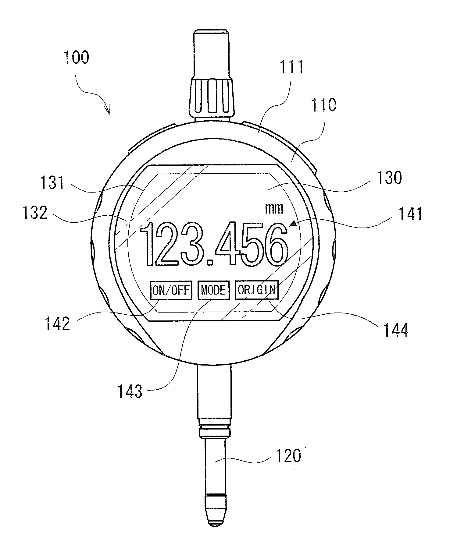
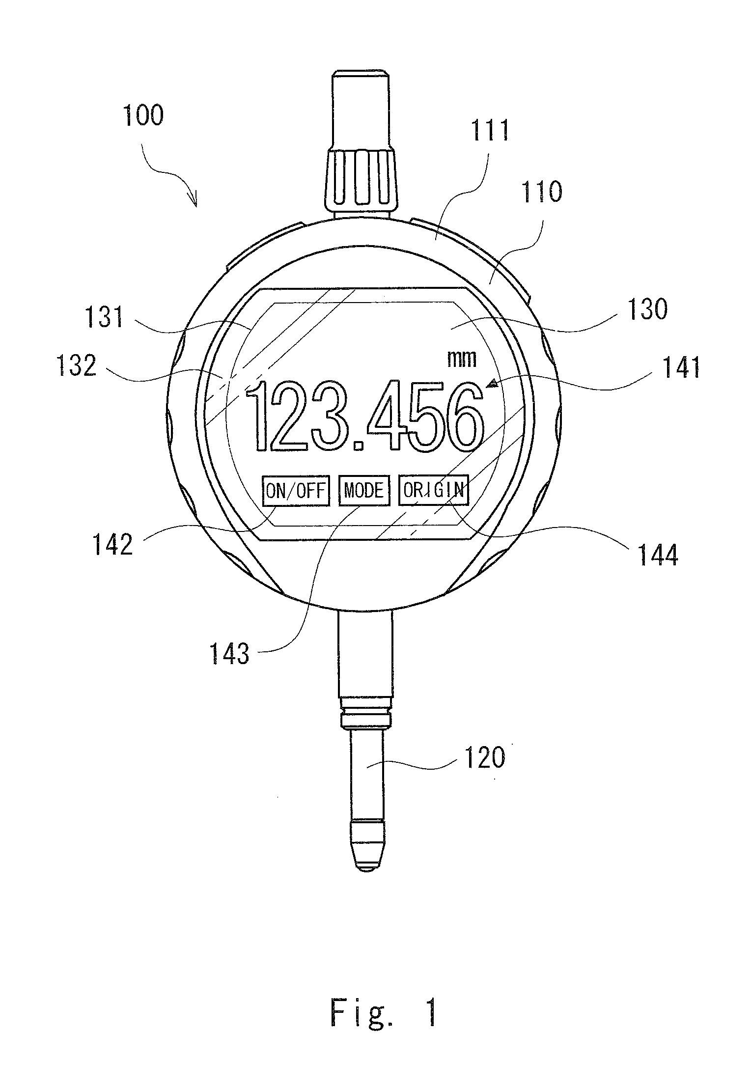
[0060]As a first exemplary embodiment, a dial gauge 100 including a touch panel display unit is explained hereinafter.

[0061]FIG. 1 is a front view of the dial gauge 100. The dial gauge 100 includes a housing unit 110, a spindle 120, and a touch panel display unit 130. The housing unit 110 has generally a cylindrical shape and includes a circular front plate 111, a circular rear plate, and a cylindrical side plate. (Note that since FIG. 1 is a front view, the rear plate and the side plate are not seen in the figure.)

[0062]By these front plate 111, rear plate, and side plate, space for housing an electronic circuit(s) is formed inside the housing unit 110.

[0063]The electronic circuit(s) may include an encoder for detecting the movement amount of the spindle 120, various arithmetic means, input detection means for detecting an input operation performed on the touch panel display unit 130, and display drive means for driving the display of the touch panel display unit 130. The spindle 1...

modified example 1

[0099]A solar panel may be further incorporated into the above-described exemplary embodiment according to the present invention for solar photovoltaic power generation.

[0100]FIG. 9 is a figure schematically showing a laminated structure of modules. From the top, a touch panel display unit 210, a semitransparent reflective sheet 220, a solar photovoltaic unit 230, and an electronic circuit module 240 are stacked.

[0101]Note that although the touch panel display unit 210 is composed of a touch panel 211 and a liquid crystal display panel 212 in the figure, other display devices such as an organic EL panel may be used instead of the liquid crystal display panel 212.

[0102]The semitransparent reflective sheet 220 may be omitted. That is, the semitransparent reflective sheet 220 may be used as appropriate depending on the type of the display device and / or the viewability of the display.

[0103]Further, the solar photovoltaic unit 230 is composed of a solar panel (solar cell(s)) 231 that is ...

modified example 2

[0112]The dial gauge 100 is used as an example in the above-described first exemplary embodiment according to the present invention. However, examples of the small tool include a micrometer and a vernier caliper, and the touch panel display unit can be applied to these small tools.

[0113]FIG. 10 shows an example of a micrometer 300 including a touch panel display unit 330.

[0114]The micrometer 300 includes a main-body frame 310, a spindle 340, and a thimble 350.

[0115]The main-body frame 310 includes a U-shaped arm section 320, an anvil 321, a sleeve 322, and a touch panel display unit 330.

[0116]The anvil 321 is disposed at one end of the U-shaped arm section 320 and the sleeve 322 is disposed at the other end of the U-shaped arm section 320. The spindle 340 is screwed into the sleeve 322 (screw is not shown) and can be moved forward / backward in the axis direction by rotating it. When the spindle 340 fully protrudes from the sleeve 322, the spindle 340 comes into contact with the anvil...


PUM


Abstract

To provide a measuring instrument having improved usability and viewability. A measuring instrument includes a touch panel display unit that receives an external input performed by physical contact and has a display function. In the touch panel display unit, a plurality of operation icons that are used to perform a complicated input operation as well as a measurement result are displayed. It is possible to provide a measuring instrument that is superior in terms of the usability and viewability. For example, a measurement mode can be selected by selecting and touching one of the plurality of operation icons displayed in the touch panel display unit.

Description

INCORPORATION BY REFERENCE[0001]This application is based upon and claims the benefit of priority from Japanese patent application No. 2012-051944, filed on Mar., 8, 2012, the disclosure of which is incorporated herein in its entirety by reference.BACKGROUND OF THE INVENTION[0002]1. Field of the Invention[0003]The present invention relates to a measuring instrument. In particular, the present invention relates to a measuring instrument equipped with a touch panel.[0004]2. Description of Related Art[0005]Various electronic measuring instruments for measuring a distance, a length, an angle, and so on, have been known. Examples of such measuring instruments include a vernier caliper, a micrometer, a dial gauge (Japanese Unexamined Patent Application Publications No. 2003-344003, No. 2003-344002, and International Patent Publication No. WO01 / 055667). Because of demands for high functionalities, such measuring instruments have started to have various functions. While they are becoming mo...

Claims


Application Information

Patent Timeline
Patent Type & Authority Applications(United States)
IPC IPC(8): G01B5/00
CPCG01B5/00G01B21/047
Inventor HAYASHI, NOBUYUKISHIRAISHI, YOSHIAKI
Owner MITUTOYO CORP
Why Eureka
Try Eureka