Shaft sealing apparatus
- Summary
- Abstract
- Description
- Claims
- Application Information
AI Technical Summary
Benefits of technology
Problems solved by technology
Method used
Image
Examples
first embodiment
[0030]Hereinafter, a first embodiment of the present invention will be described in detail with reference to the drawings.
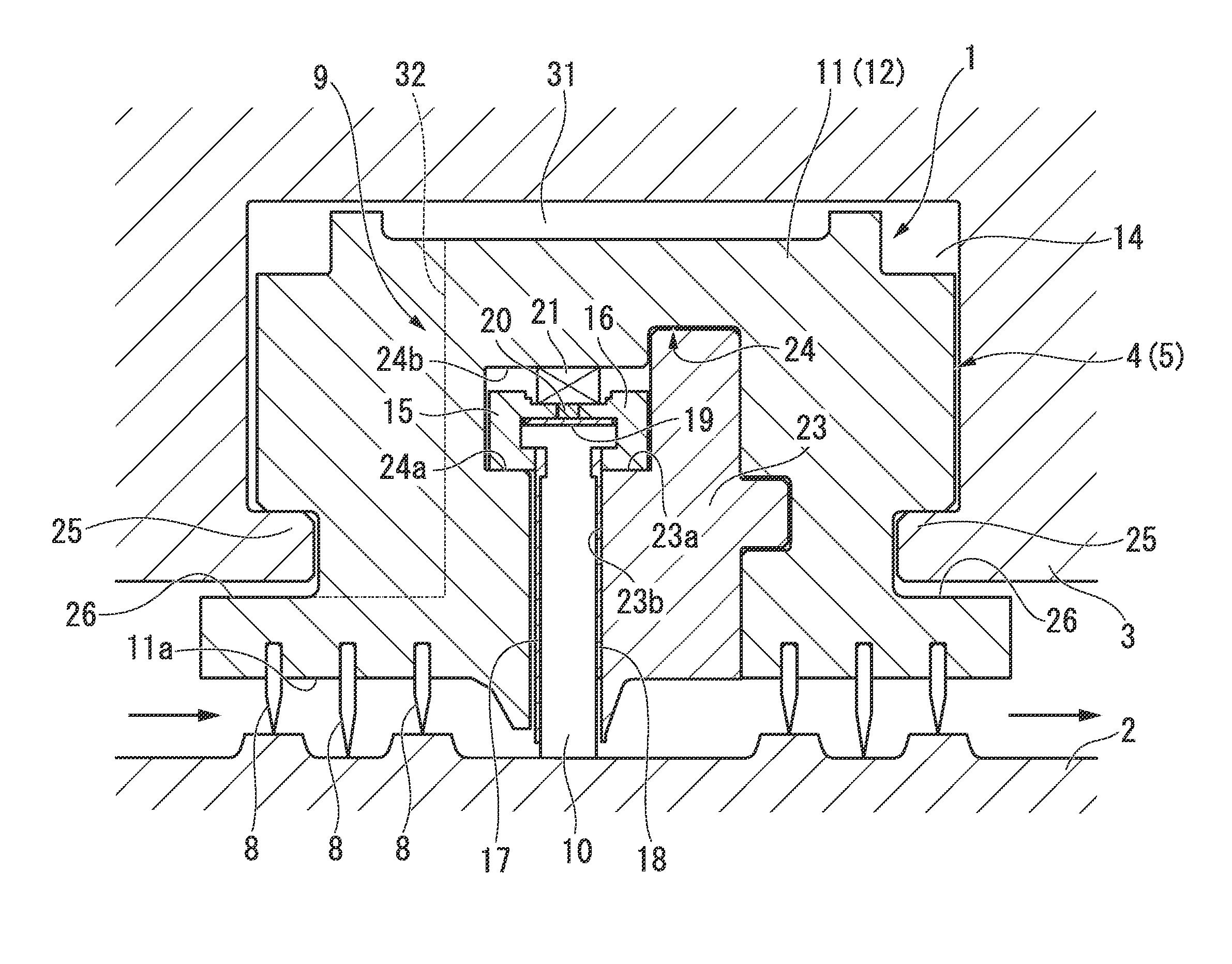
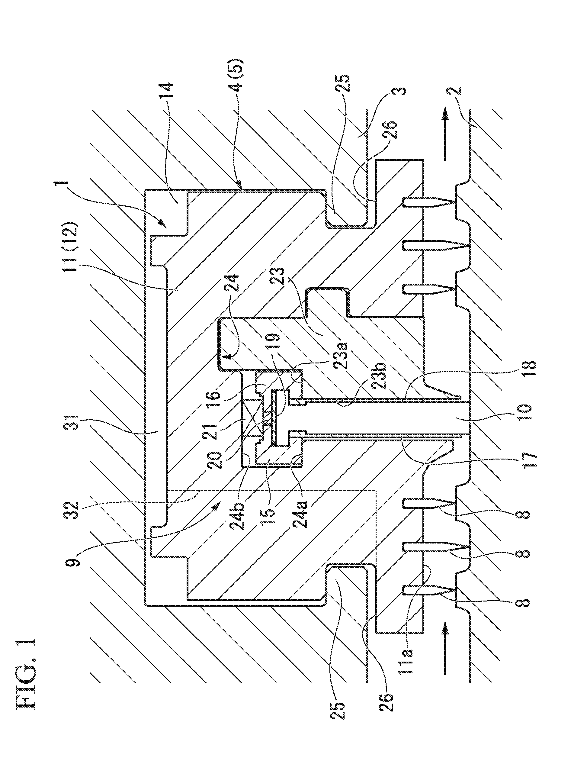
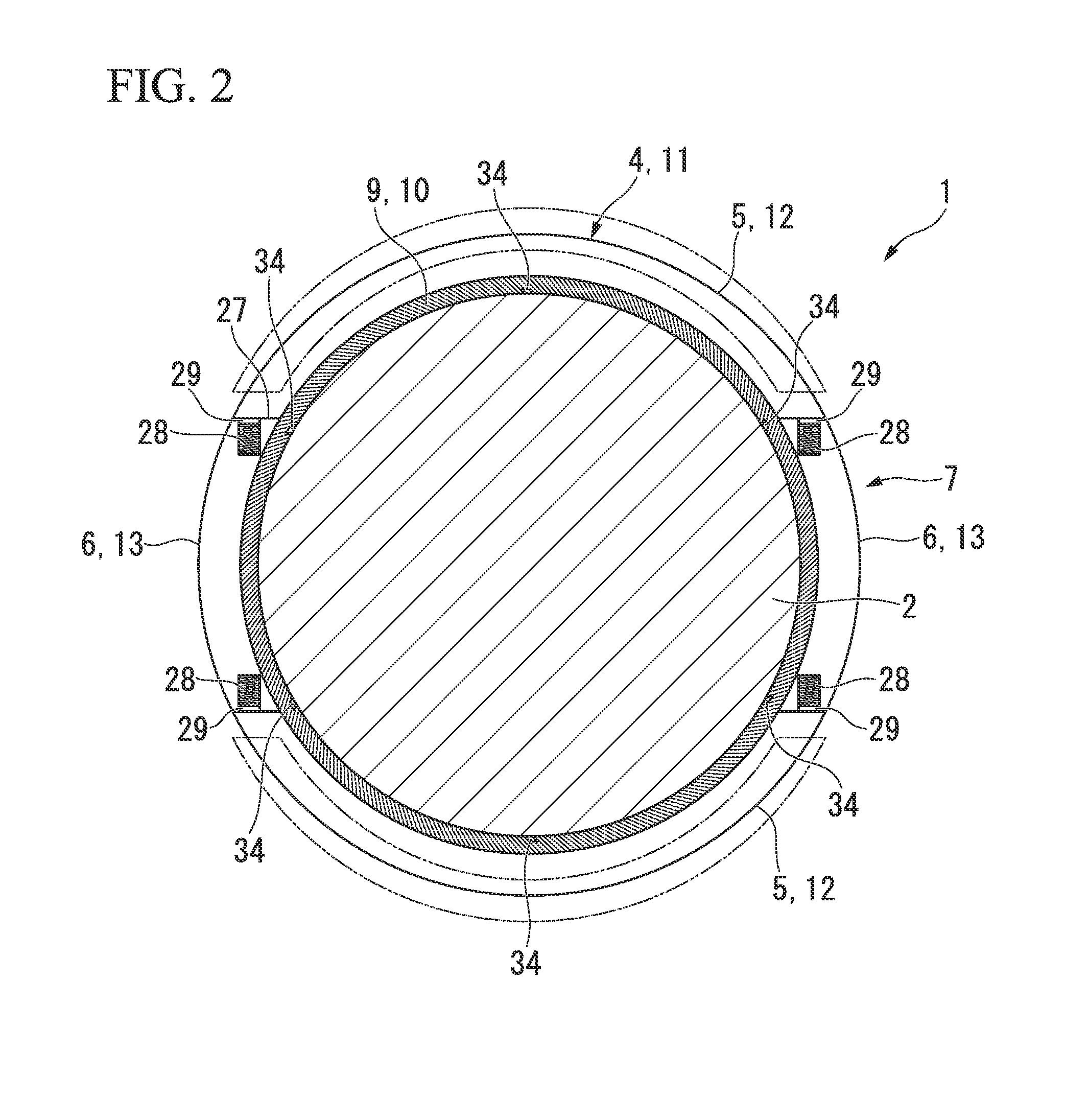
[0031]A shaft sealing apparatus 1 of the present embodiment is applied to, for instance, a gas turbine (rotating machine). As shown in FIGS. 1 and 2, the shaft sealing apparatus 1 of the present embodiment is installed in an annular space between a rotor 2 and a stator 3. The shaft sealing apparatus 1 is a device that divides the annular space into a low-pressure side region and a high-pressure side region. An inner circumferential surface of the stator 3 which faces an outer circumferential surface of the rotor 2 is formed with a recess 14 that is formed around a central axis of the rotor 2 in an annular shape, and the shaft sealing apparatus 1 is housed in the recess 14.
[0032]As shown in FIG. 2, the shaft sealing apparatus 1 includes a sealing apparatus body 4 supported on the stator 3, and an automatic clearance adjusting mechanism 7 automatically adjusting a ...
second embodiment
[0078]FIG. 7 is a schematic configuration view showing a shaft sealing apparatus 1B according to a second embodiment of the present invention. In the present embodiment, portions different from the first embodiment described above will be mainly described, and similar portions will not be described.
[0079]As shown in FIG. 7, in the shaft sealing apparatus 1B according to the present embodiment, in place of the communicating parts 34 (see FIG. 2) of the first embodiment, bypass communicating parts 36 are provided as bypass channels. The bypass communicating parts 36 are formed by passing through a seal ring 11 and a mounting piece 23 in such a way as to bypass a seal body 9, and cause a high-pressure side region and a low-pressure side region to communicate with each other. Further, the plurality of bypass communicating parts 36 are provided in a circumferential direction of the seal ring 11.
[0080]At the time of rated operation, when a movable sealing apparatus body 5 is located at a ...
third embodiment
[0083]FIG. 8 is a schematic configuration view showing a shaft sealing apparatus 1C according to a third embodiment of the present invention. In the present embodiment, portions different from the first embodiment described above will be mainly described, and similar portions will not be described.
[0084]As shown in FIG. 8, in the shaft sealing apparatus 1C according to the present embodiment, in addition to the configuration of the first embodiment, a brush seal 38 is provided. The brush seal 38 is a toric part mounted on the most upstream side of a seal ring 11, and is divided into a plurality of segments, for instance six segments, in a circumferential direction. The brush seal 38 is made up of a support part 39 and numerous thin wires 40 welded to the support part 39. Tips of the wires 40 protrude toward a side of the rotor 2.
[0085]The plurality of wires 40 is elastically deformed, and thereby the brush seal 38 performs sealing.
[0086]Next, a difference in pressure variation of th...
PUM
 Abstract
Description
Claims
Application Information
 - R&D
- Intellectual Property
- Life Sciences
- Materials
- Tech Scout
- Unparalleled Data Quality
- Higher Quality Content
- 60% Fewer Hallucinations
Browse by: Latest US Patents, China's latest patents, Technical Efficacy Thesaurus, Application Domain, Technology Topic, Popular Technical Reports.
© 2025 PatSnap. All rights reserved.Legal|Privacy policy|Modern Slavery Act Transparency Statement|Sitemap|About US| Contact US: help@patsnap.com


