Self-Propelled Road Milling Machine For Milling Road Surfaces, In Particular Large-Scale Milling Machine, And Method For Milling Road Surfaces

a road surface and self-propelled technology, which is applied in the direction of surface mining, roads maintainence, roads, etc., can solve the problems of large milling depth and the inability of the machine operator to follow a curve, and achieve the effect of improving manuverability

Active Publication Date: 2013-09-12
WIRTGEN GMBH
View PDF10 Cites 7 Cited by
  • Summary
  • Abstract
  • Description
  • Claims
  • Application Information

AI Technical Summary

Benefits of technology

[0011]It is an object of the present invention to provide a self-propelled road milling machine of the type described above, and a method for milling road surfaces, which machine is more universally usable and whose maneuverability is improved.

Problems solved by technology

The milling roller housing is not adjustable in height relative to the machine frame such that the overall machine weight can be transmitted to the milling roller to produce high cutting forces and thus a large milling depth.
So far large-scale milling machines have been used mainly for milling large surfaces only, inter alia, because of their limited maneuverability, wherein, depending on the course of the road, it has been possible to perform milling work in curves of the road having a large curve radius.
In particular during milling work performed towards the inside relative to the zero side large-scale milling machines are problematic in that it has not been possible for the machine operator to follow a curve with a narrow curve radius.
This is disadvantageous in that the road milling machine having its zero side on the right-hand side, as seen in the direction of travel, has to travel opposite to the moving traffic when a road cannot be completely closed when roadwork is performed.
This is disadvantageous in that the trucks receiving the milled-off product in front of the road milling machine must also travel opposite to the traffic flow to the front side of the road milling machine and then travel away from there.
The machine concerned is not a large-scale milling machine which can produce large cutting forces since the milling roller is supported such that it is pivotable about a horizontal axis and rests on the ground merely due to its dead weight.

Method used


Image

  • Self-Propelled Road Milling Machine For Milling Road Surfaces, In Particular Large-Scale Milling Machine, And Method For Milling Road Surfaces
  • Self-Propelled Road Milling Machine For Milling Road Surfaces, In Particular Large-Scale Milling Machine, And Method For Milling Road Surfaces
  • Self-Propelled Road Milling Machine For Milling Road Surfaces, In Particular Large-Scale Milling Machine, And Method For Milling Road Surfaces

Examples


Embodiment Construction

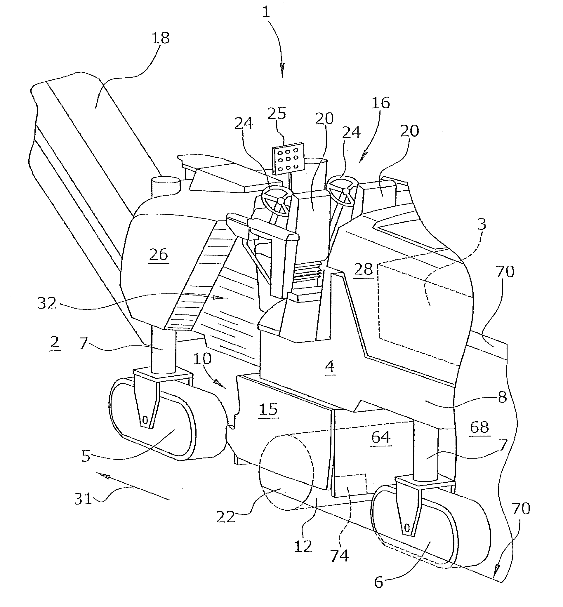
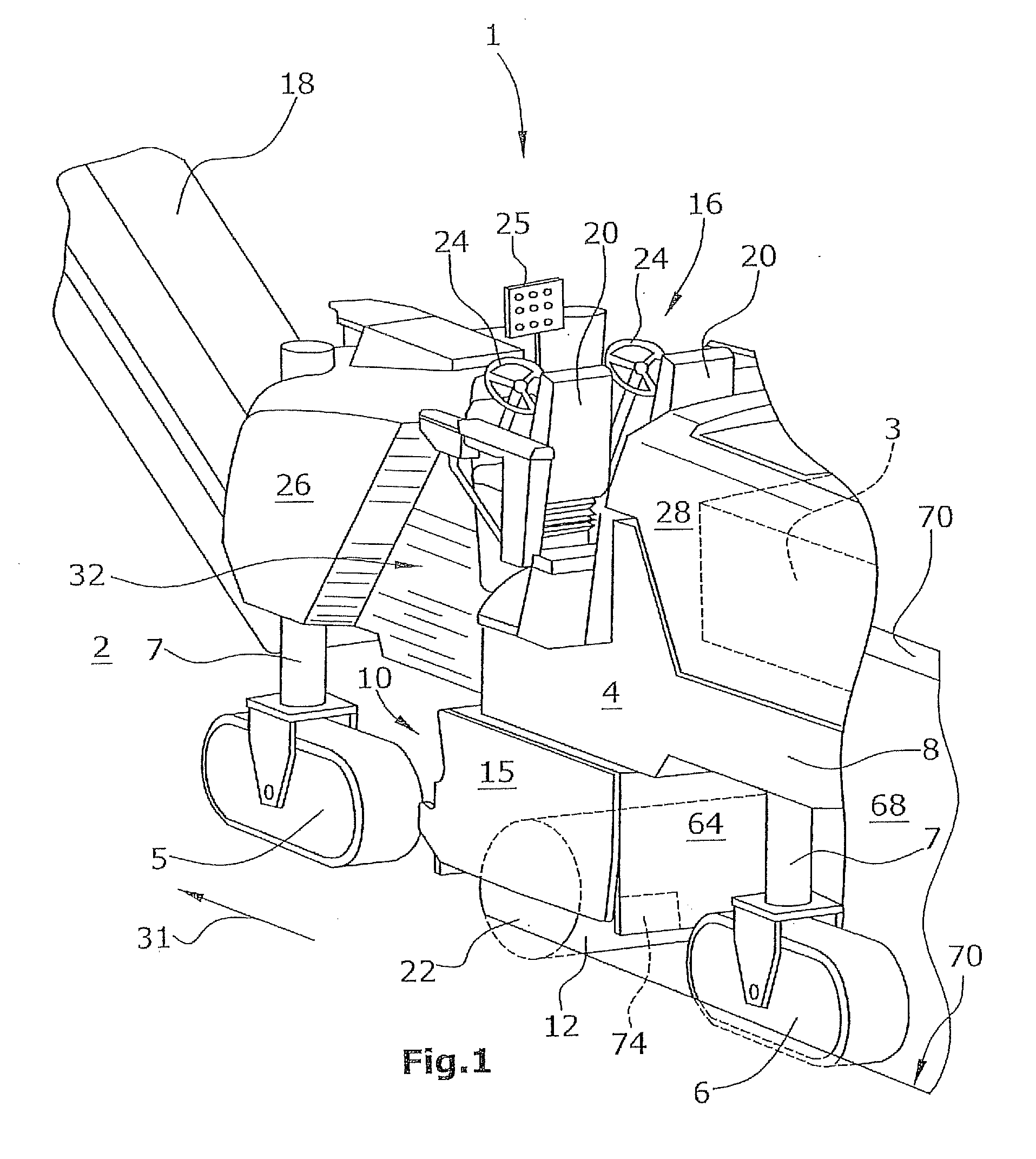
[0047]FIG. 1 shows a road milling machine 1, in particular a large-scale milling machine, comprising a machine frame 8 and a chassis 4 including front and rear traveling gears 5,6, as seen in the direction of travel 31. The traveling gears 5,6 define a steerable front axle and a steerable rear axle. The chassis 4 is connected with the machine frame 8 via lifting columns 7 with the aid of which the distance of the machine frame 8 to a road surface 2 is adjustable. Each chassis axle comprises at least one crawler-type traveling gear 5,6 or a wheel-type traveling gear.

[0048]At a front side, as seen in the direction of travel, of the road milling machine 1 a vertically and laterally pivotable conveyor belt means 18 for removing the milled-off milling product is arranged.

[0049]The front and rear traveling gears 5,6 of the chassis 4 may be crawler-type traveling gears or wheel-type traveling gears.

[0050]The machine frame 8 comprises lateral outer sides 26,28 essentially extending vertical...


PUM


Abstract

In a self-propelled road milling machine for milling road surfaces comprising a milling roller housing arranged at the machine frame between the front and rear chassis axles, it is provided that the rear end, as seen in the direction of travel, of the milling roller housing is flush with a height adjustable stripper shield which laterally rests in the milling track of the milling roller and resiliently against a milling edge of the milling track extending orthogonally to the road surface.

Description

BACKGROUND OF THE INVENTION[0001]1. Field of the Invention[0002]The invention relates to a self-propelled road milling machine for milling road surfaces, in particular large-scale milling machines, and a method for milling road surfaces.[0003]2. Description of the Prior Art[0004]Road milling machines having a milling width of approximately 1500 mm and more are referred to as large-scale milling machines, for example. Such road milling machines have a large weight and are thus normally supported by a chassis comprising crawler-type traveling gears. The milling roller is supported at the machine frame between the traveling gears of the front axle and the rear axle in spaced relationship to the axles. Large-scale milling machines comprise a height adjustable chassis including front and rear traveling gears which define the front axle and the rear axle, respectively. The machine frame is supported by the chassis, wherein between the axles of the front and rear traveling gears a milling ...

Claims


Application Information

Patent Timeline
Patent Type & Authority Applications(United States)
IPC IPC(8): E01C23/12
CPCE01C23/088E01C23/127
Inventor EMME, HARDYBARIMANI, CYRUSSALZ, ANDREASHAEHN, GUENTER
Owner WIRTGEN GMBH
Why Eureka
Try Eureka