
Field emission apparatus and hand-held nondestructive inspection apparatus

a field emission device and non-destructive inspection technology, which is applied in the manufacture of electric discharge tubes/lamps, vacuum tube vessels/containers/shields, electrode systems, etc., can solve the problem of large applied voltage v for obtaining the required emission current, the characteristic change (degradation) of the carbon nano-tube itself, and the risk of electric discharge caused by gases generated in vacuum vessels, etc., to achieve the effect of extending the creepage distance, reducing size and weigh

Inactive Publication Date: 2013-09-12
MICRO X JAPAN
View PDF5 Cites 3 Cited by
  • Summary
  • Abstract
  • Description
  • Claims
  • Application Information

AI Technical Summary

Benefits of technology

The patent design improves the efficiency of an electron emission device by increasing the distance between the parts that produce heat (the flange). The invention also separates components, making them smaller and easier to insulate, which reduces the need for insulation oil and reduces size and weight.

Problems solved by technology

However, the fact that the value of the applied voltage V for obtaining the required emission current is large also has issues such as the emergence of characteristic change (degradation) of the carbon nano-tube itself, a requirement for a special power supply due to the high voltage required to obtain a certain level of current, and the construction of the cold cathode luminescent lamp.
As aforementioned, for a field emission device having a cold cathode with carbon film structures and with superior I-V characteristics, there is a risk of an electric discharge caused by gases (creeping discharge and flashovers) generated within the vacuum vessel in which the temperature rises significantly (in particular, on the anode side) owing, for example, to electron beams emitted from the cold cathode.
A large quantity of electron beams entering into the anode sometimes heats the anode to 500 C. degrees or above, leading to deformation of the anode.
However, such a vacuum vessel elongated in the direction of electron beam emission has a longer distance between cold cathode and anode, and aligning them while evacuating calls for a highly specialized vacuum technology, adding further costs to the vacuum vessel itself.
Another idea may be that the anode is elongated in the direction of electron beam emission to shorten the distance between cold cathode and anode, but the longer the length of the anode is in the direction of the electron beam emission (distance between the electron beam hitting area and the outer surface of the vacuum vessel), the lesser the exothermic efficiency becomes, thus leading to difficulties in increasing the capacity of the vacuum vessel (Vxi).
This may also lead to a field emission device much larger in size.

Method used


Image

  • Field emission apparatus and hand-held nondestructive inspection apparatus
  • Field emission apparatus and hand-held nondestructive inspection apparatus
  • Field emission apparatus and hand-held nondestructive inspection apparatus

Examples


Embodiment Construction

[0061]The following are detailed explanations on the implementation mode of the field emission device under the present invention using drawings. Where appropriate, further detailed explanations are omitted for those equivalent to FIG. 20-FIG. 22 and replaced with the same reference signs.

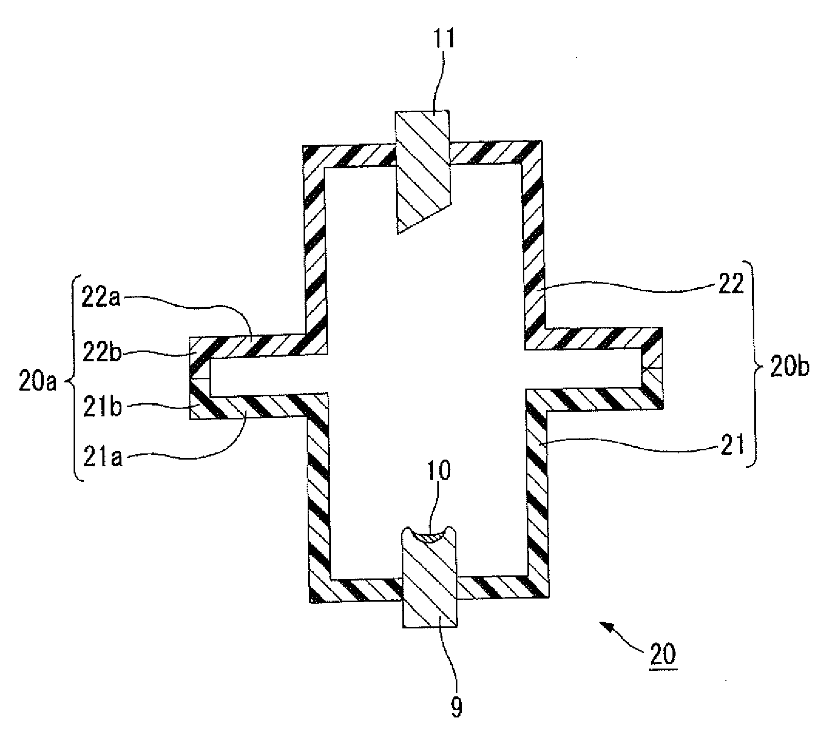
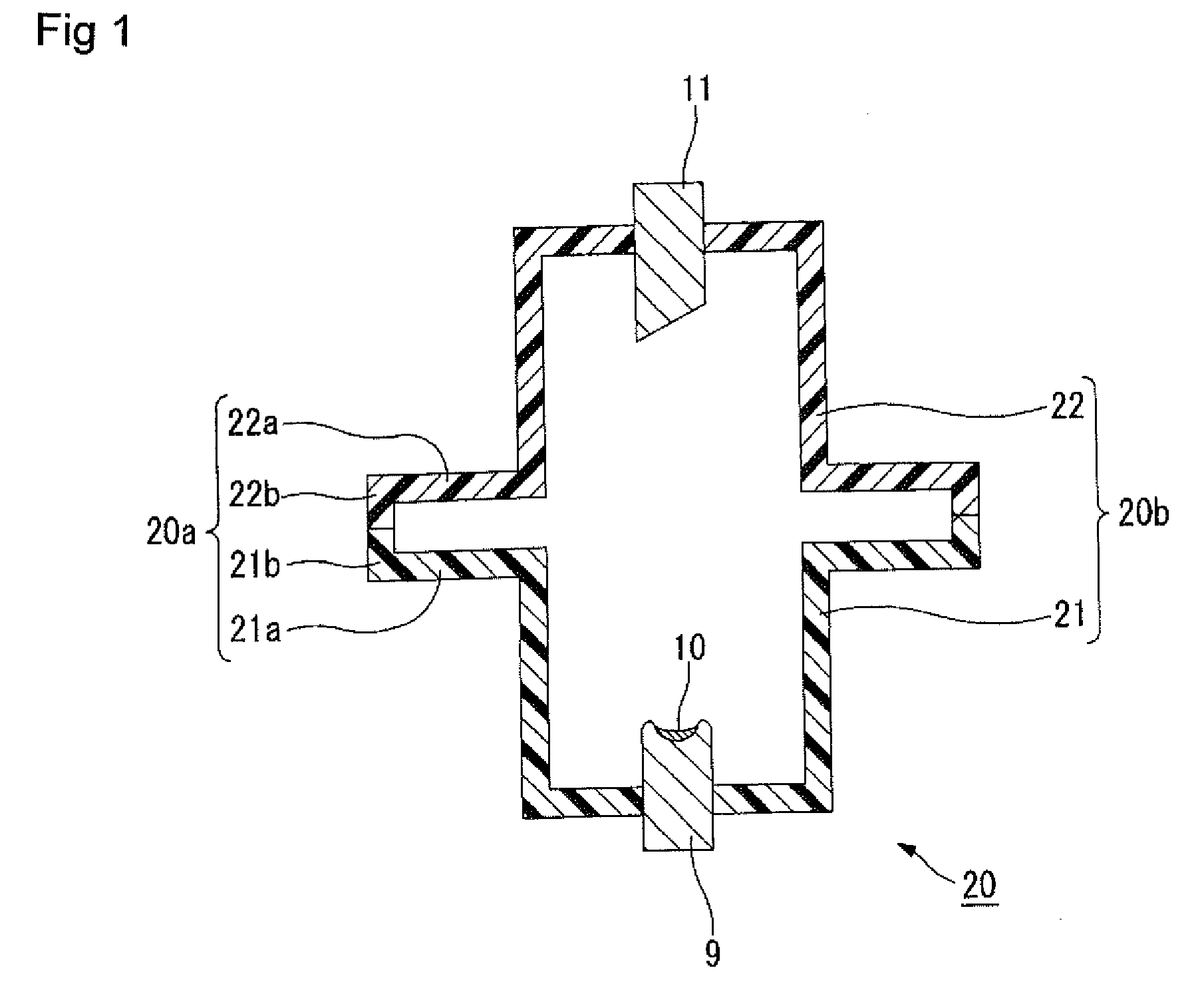
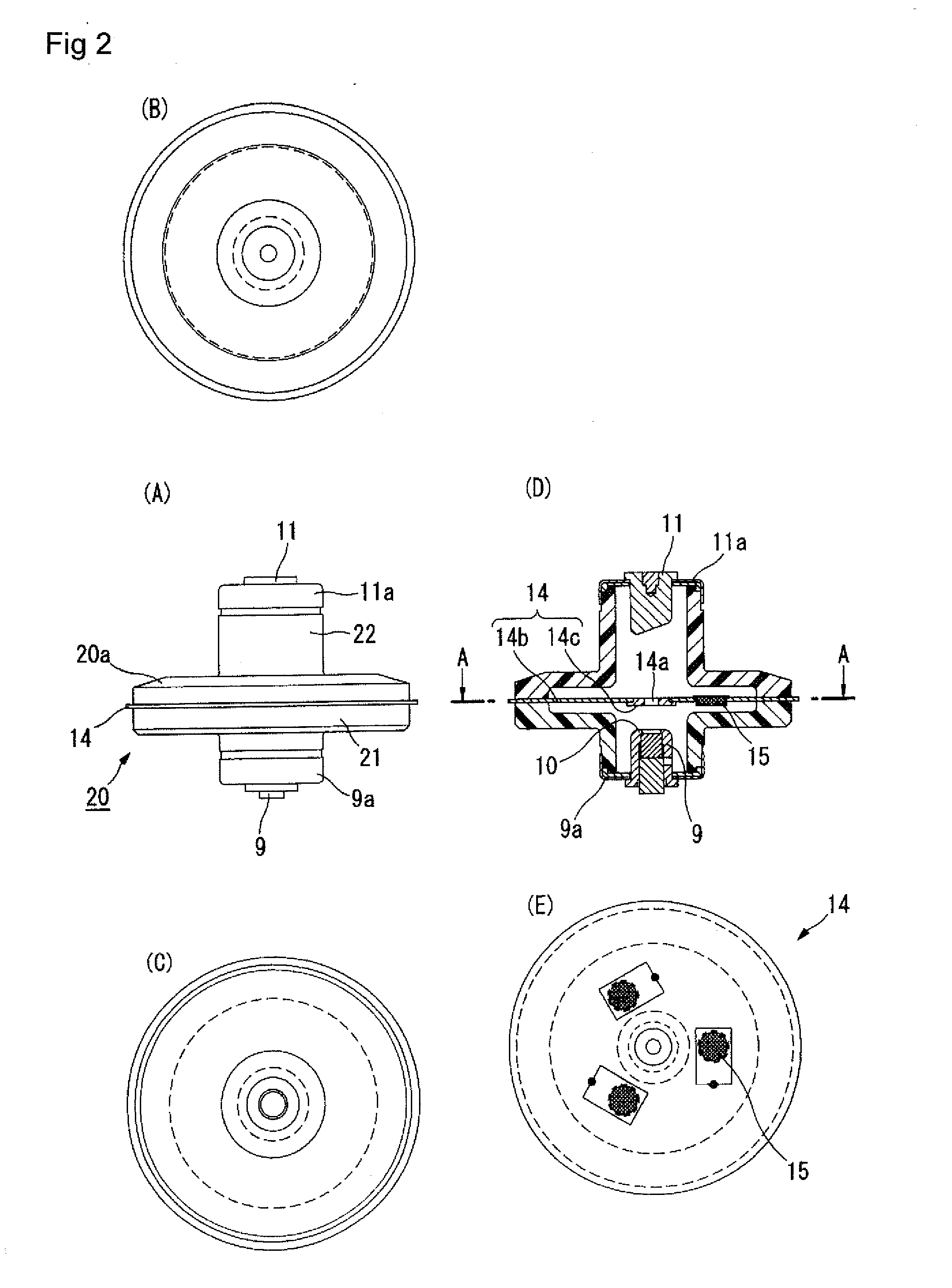
[0062]The primary invention is with the elongation of the radius of the vacuum vessel in the direction at right angles to the direction of the electron beam emission at the place between the cold cathode and the anode (for example, the place where grid electrode such as electron lens is positioned) and not with the elongation of the radius of the vacuum vessel in the direction of the electron beam emission as shown in FIG. 21, and by the vacuum vessel having a flange portion with a hollow formed by the elongated side walls, the exothermic efficiency is enhanced without extending the distance between the cold cathode and the anode or elongating the length of the anode in the direction of the electro...


PUM


Abstract

In the present invention, heat dissipation is improved by extending the creepage distance in a vacuum vessel according to the size of a flange portion, without lengthening the vacuum vessel in the direction in which an electron beam is emitted.A vacuum vessel (20) in which a flange portion (20a) having a hollow portion between a cold cathode (9) and an anode (11) is formed is used.One example is a vacuum vessel (20) in which a cold cathode vessel (21) and an anode vessel (22), both cylindrically shaped, are communicated with each other and a hollow flange portion (20a) is formed between the vessels (21, 22).A focusing electrode (14) and a getter material (15), for example, are disposed in the hollow portion of the flange portion (20a).A cold cathode (9) which has a guard electrode on the outer side of the periphery of a carbon film structure (10) formed on a substrate (7) may be used. The carbon film structure (10) may be formed in the middle of an electrode surface of the substrate (7).

Description

TECHNICAL FIELD[0001]This invention relates to a field emission device and a portable non-destructive inspection device having electron emitters and being applicable to various kinds of electron tubes, lighting device, X-ray devices, etc.BACKGROUND ART[0002]Field emission is a phenomenon whereby electrons are emitted into a vacuum by the concentration of an electric field, and as an emitter for this type of field emission the carbon nano-tube, for example, is attracting attention. A carbon nano-tube has favorable field emission properties owing to its extreme thinness and high aspect ratio and is said to be beneficial in obtaining field emission electron elements. There have been attempts to apply it as a field emission device for electron tubes, lighting device, etc.[0003]Field emission property (‘I-V characteristics’) means a property described by a curve that shows the relationship between voltage (V) and emission current (I) when voltage (V) is applied between the anode (target)...

Claims


Application Information

Patent Timeline
IPC IPC(8): H01J19/54H01J19/42
CPCH01J35/065H01J2201/30469H01J19/54H01J2237/16H01J19/42H01J2235/062
Inventor ISHIGURO, YOSHIHISAHABA, MASANORI
Owner MICRO X JAPAN
Learn More