Wireless Lighting Control System

a control system and wireless technology, applied in the field of lighting, can solve the problems of current requirements of lighting devices, and achieve the effect of easy installation and transfer of lighting

Active Publication Date: 2013-09-12
ILUMI SOLUTIONS
View PDF1 Cites 30 Cited by
  • Summary
  • Abstract
  • Description
  • Claims
  • Application Information

AI Technical Summary

Benefits of technology

[0007]The present invention provides an easily installed and transferable lighting and home automation solution because special or customized installation is not required. The present invention presents a solution to controlling and programming lighting devices, such that the color and brightness of any individual light or a group of lights can be manually or automatically controlled using a wireless interface. A user has the flexibility to personalize the color, atmosphere, and mood of a room to better fit ones preference, time of day, or occasion at hand.
[0008]Additionally, since the present invention requires no installation, the solution is fully portable and can be removed and reused in other locations throughout the long life of the device. Essentially, the present invention is an automation and custom lighting solution that can travel with you.
[0009]Automation and dimming of the lighting devices save more energy than is consumed by the additional components of the lighting device. Moreover, using on / off signals having specified cycle times to produce a blended light reduce the current requirements of the lighting device. Lastly, holistically speaking the iLumi solution itself will help to drive the adoption of LED bulbs, providing an LED solution whose value outweighs its price.

Problems solved by technology

Moreover, using on / off signals having specified cycle times to produce a blended light reduce the current requirements of the lighting device.

Method used


Image

  • Wireless Lighting Control System
  • Wireless Lighting Control System
  • Wireless Lighting Control System

Examples


Embodiment Construction

[0074]While the making and using of various embodiments of the present invention are discussed in detail below, it should be appreciated that the present invention provides many applicable inventive concepts that can be embodied in a wide variety of specific contexts. The specific embodiments discussed herein are merely illustrative of specific ways to make and use the invention and do not delimit the scope of the invention.

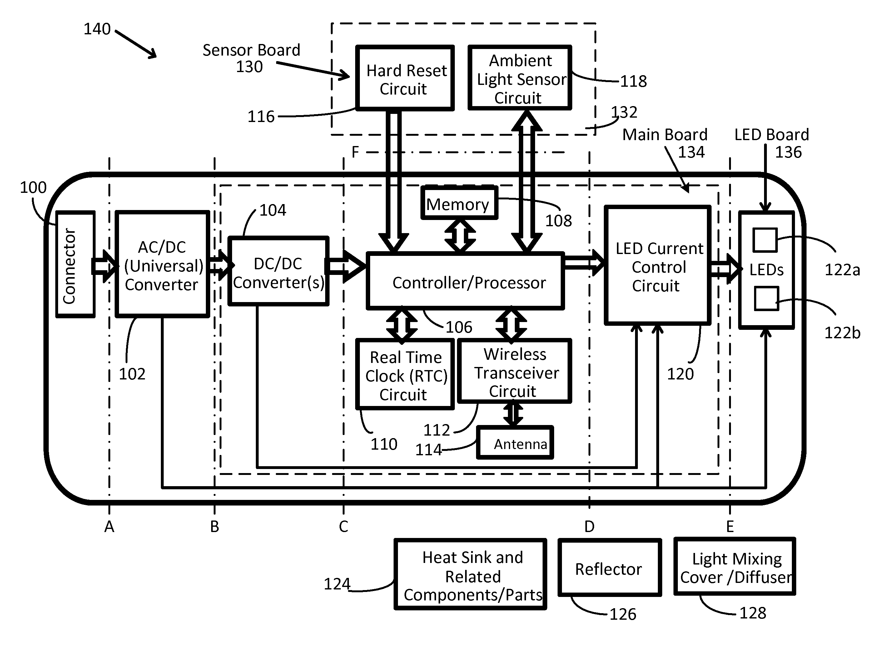
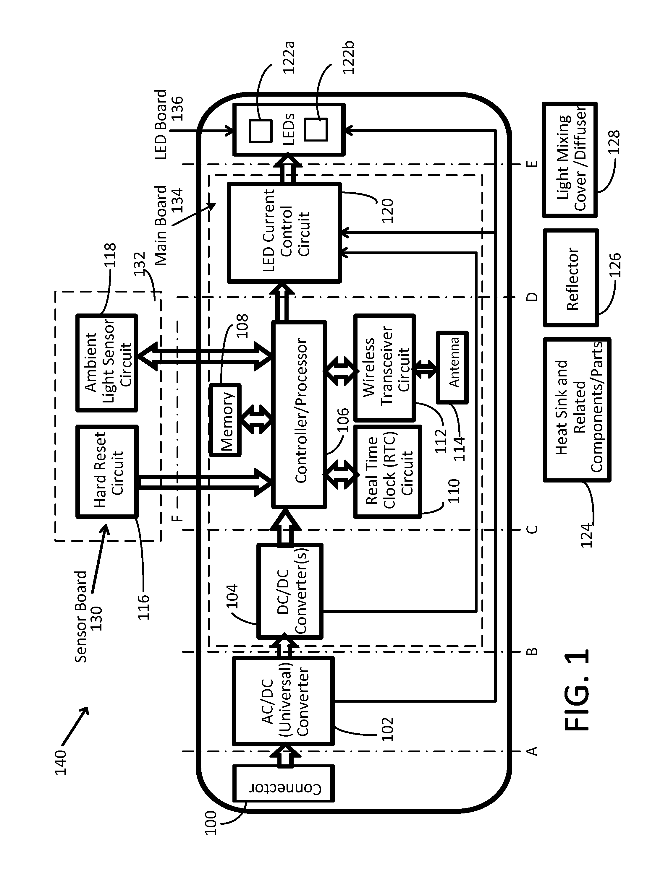
[0075]The present invention provides an easily installed and transferable lighting and home automation solution because special or customized installation is not required. The present invention presents a solution to controlling, programming, and automating lighting devices, such that the color and brightness of any individual light or a group of lights can be manually or automatically controlled using a wireless interface. A user has the flexibility to personalize the color, atmosphere, and mood of a room to better fit ones preference, time of day, or occasion a...


PUM


Abstract

A lighting device includes a DC / DC power converter, a controller / processor electrically connected to the DC / DC power converter, a light emitting diode (LED) current control circuit communicably coupled to the controller / processor and electrically connected to the DC / DC power converter, and two or more LEDs comprising at least a first color LED and a second color LED electrically connected to the LED current control circuit. The LED current control circuit provides an on / off signal having a cycle time to each LED in response to one or more control signals received from the controller / processor such that the two or more LEDs produce a blended light having a specified color based on how long each LED is turned ON and / or OFF during the cycle time.

Description

CROSS-REFERENCE TO RELATED APPLICATIONS[0001]This application claims priority to and is a continuation application of U.S. patent application Ser. No. 13 / 417,322, filed Mar. 11, 2012, and entitled “Wireless Lighting Control System”, which is a non-provisional patent application of U.S. Provisional Application Ser. No. 61 / 464,917, filed Mar. 11, 2011, and entitled “Specialty Lighting and Control Therefor.” In addition, this application claims priority to PCT Patent Application Serial Number PCT / US2012 / 037369, filed May 10, 2012, and entitled “Wireless Lighting Control System.” The foregoing applications are hereby incorporated by reference in their entirety.BACKGROUND OF THE INVENTION[0002]1. Field of the Invention[0003]The present invention relates generally to the field of lighting and, more particularly, to a specialty lighting device and control process for individual or simultaneous adjustment, automation, and programming of an individual or network of such lighting devices thro...

Claims


Application Information

Patent Timeline
Patent Type & Authority Applications(United States)
IPC IPC(8): H05B37/02H05B44/00
CPCH05B33/0845H05B33/0842H05B33/0863H05B37/0218H05B37/0281H05B37/0272H05B45/20H05B47/19Y02B20/40H05B45/37H05B45/12H05B45/10Y02B20/30H05B47/16H05B45/22H05B47/11
Inventor BORA, SWAPNILEGAN, COREY
Owner ILUMI SOLUTIONS
Why Eureka
Try Eureka