LED lighting control apparatus and method based on visible light communication

a technology of lighting control apparatus and communication method, which is applied in the direction of lighting and heating apparatus, electroluminescent light sources, fixed installations, etc., to achieve the effect of saving energy, efficient control, and reducing the power consumption of lighting means

Inactive Publication Date: 2013-09-12
ELECTRONICS & TELECOMM RES INST
View PDF2 Cites 61 Cited by
  • Summary
  • Abstract
  • Description
  • Claims
  • Application Information

AI Technical Summary

Benefits of technology

[0008]Accordingly, the present invention has been made keeping in mind the above problems occurring in the prior art, and an object of the present invention is to provide an LED lighting control apparatus and method based on visible light communication, which efficiently control a lighting means by transmitting and receiving environmental information about surroundings and status information about the lighting means over a communication network configured based on visible light communication, thus reducing power consumption of the lighting means and ultimately saving energy.

Problems solved by technology

The VLC technology applied to a lighting means which uses an LED light source is limited in that communication is possible only in an area receiving the light, and a central processing unit can merely recognize status information about the lighting means over a lighting control network Further, such VLC technology is inconvenient in that in order to examine whether the desired illuminance has been output from a corresponding lighting means, illuminance is manually measured using an illuminance meter (a lux meter) under the corresponding lighting means, and in that the CPU newly controls lighting based on the values measured by the lux meter.

Method used


Image

  • LED lighting control apparatus and method based on visible light communication
  • LED lighting control apparatus and method based on visible light communication
  • LED lighting control apparatus and method based on visible light communication

Examples


Embodiment Construction

[0033]Preferred embodiments of the present invention will be described in detail below with reference to the accompanying drawings to such an extent that those skilled in the art can easily implement the technical spirit of the present invention. Reference now should be made to the drawings, in which the same reference numerals are used throughout the different drawings to designate the same or similar components. In the following description, redundant descriptions and detailed descriptions of known elements or functions that may unnecessarily make the gist of the present invention obscure will be omitted.

[0034]Hereinafter, an LED lighting control apparatus and method based on visible light communication according to an embodiment of the present invention will be described in detail with reference to the attached drawings.

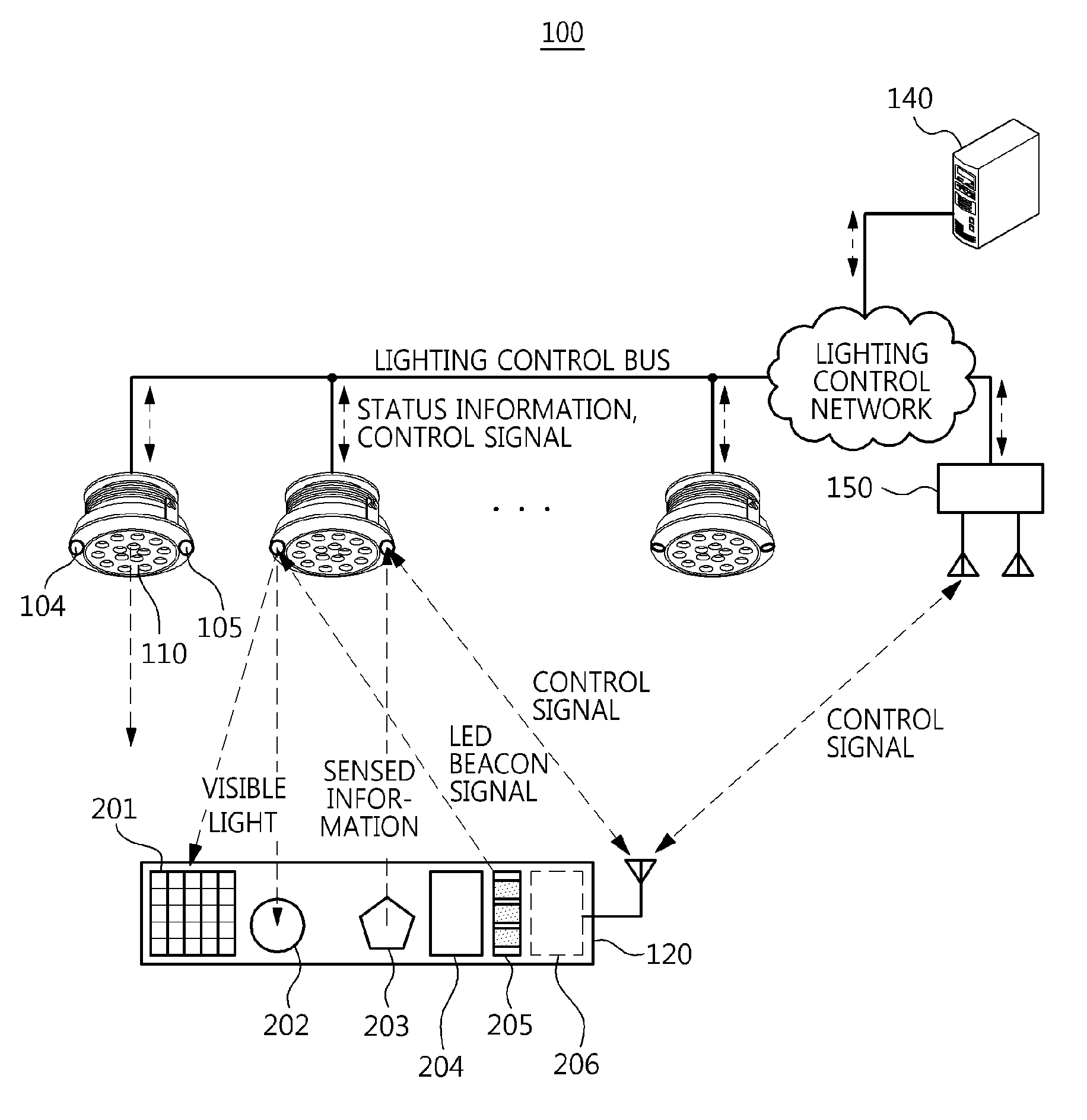
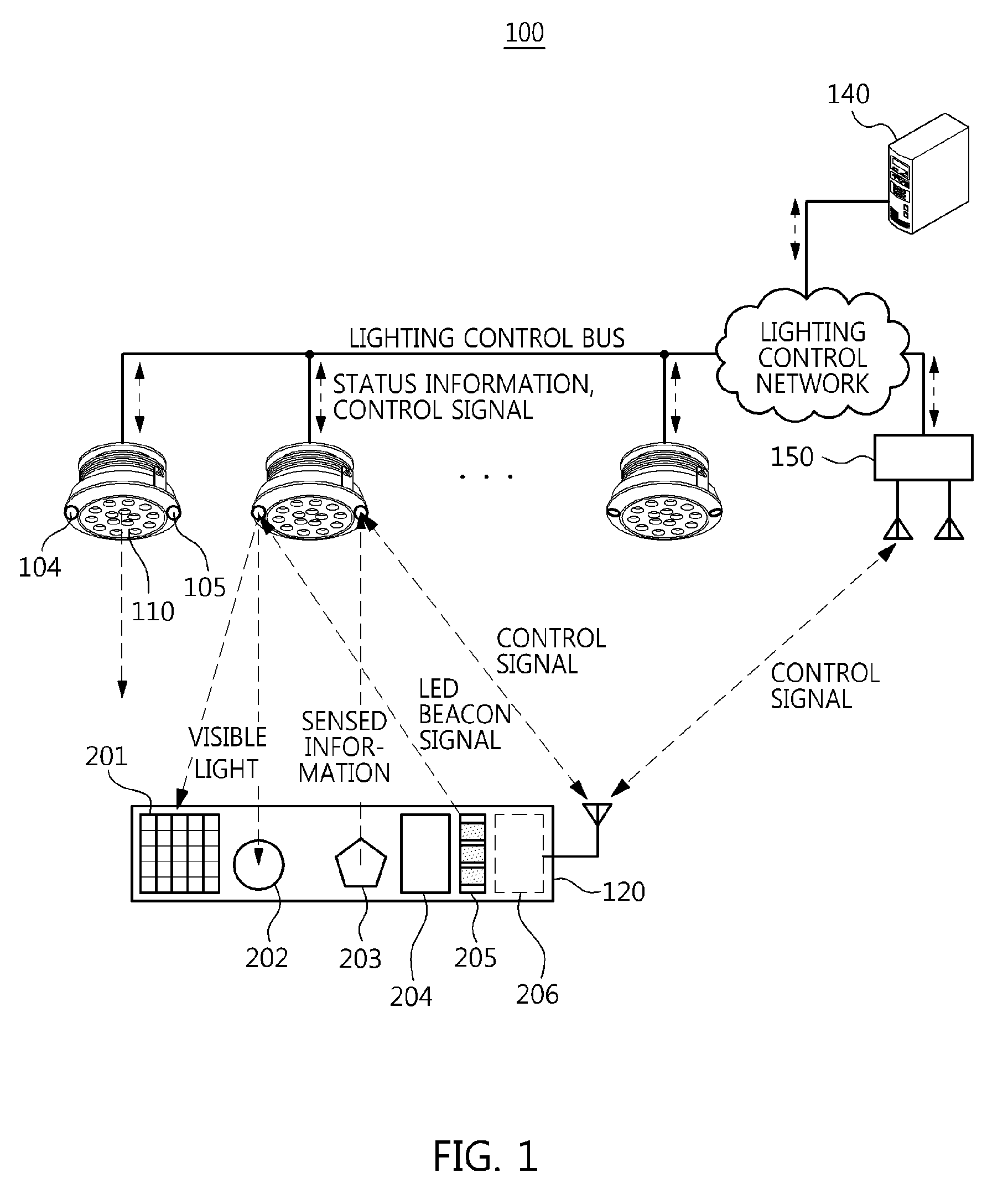
[0035]FIG. 1 is a diagram showing the configuration of an LED lighting control apparatus based on visible light communication according to an embodiment of the pr...


PUM


Abstract

Disclosed herein is an LED lighting control apparatus and method based on visible light communication. The LED lighting control apparatus includes lighting information collection means for collecting status information about lighting means and environmental information about surroundings of the lighting means, and transmitting the collected information to lighting control means. The lighting information collection means includes a visible light reception processing unit for receiving the status information about the lighting means contained in a visible light signal emitted from the lighting means, a lighting information analysis unit including a plurality of environmental information sensors for detecting the environmental information about the surroundings of the lighting means, the lighting information analysis unit analyzing the environmental information detected by the environmental information sensors, and a lighting information control unit for collecting the status information and the analyzed environmental information and transmitting the collected information to the lighting control means.

Description

CROSS REFERENCE TO RELATED APPLICATION[0001]This application claims the benefit of Korean Patent Application No. 10-2012-0025068, filed on Mar. 12, 2012, which is hereby incorporated by reference in its entirety into this application.BACKGROUND OF THE INVENTION[0002]1. Technical Field[0003]The present invention relates generally to a Light-Emitting Diode (LED) lighting control apparatus and method based on visible light communication. More particularly, the present invention relates to an apparatus and method that collect status information about a lighting means and environmental information about the surroundings of the lighting means, and then control lighting based on visible light communication.[0004]2. Description of the Related Art[0005]A lighting means that uses a Light-Emitting Diode (LED) as a light source can realize visible light communication (hereinafter referred to as “VLC”) by utilizing fast ON / OFF operations of the LED light source.[0006]The VLC technology applied t...

Claims


Application Information

Patent Timeline
Patent Type & Authority Applications(United States)
IPC IPC(8): H05B33/08H05B44/00
CPCH05B33/0854Y02B20/46H05B37/0272H05B37/0218H05B45/10H05B47/11H05B47/19Y02B20/40H05B47/195F21S8/03H04B10/11
Inventor KIM, YOU-JINKANG, TAE-GYUKIM, HYUN-JONGKIM, IN-SUKIM, DAE-HOJANG, IL-SOONJEONG, JIN-DOOLIM, SANG-KYUPARK, SEONG-HEE
Owner ELECTRONICS & TELECOMM RES INST
Why Eureka
Try Eureka