Transformer capable of suppressing common mode current and power converter thereof

a transformer and common mode current technology, applied in the field of transformers, can solve the problems of only using foil shielding layers, common mode noise in power converters, so as to reduce common mode current, reduce production costs, and improve production efficiency

Active Publication Date: 2013-09-12
DELTA ELECTRONICS SHANGHAI CO LTD
View PDF5 Cites 11 Cited by
  • Summary
  • Abstract
  • Description
  • Claims
  • Application Information

AI Technical Summary

Benefits of technology

[0026]In the present invention, by using the transformer capable of suppressing the common mode current, there are a first shielding winding and a second shielding winding disposed on the same shielding winding layer. The voltage jump direction of the first shielding winding is constantly opposite to that of the second shielding winding. Thus, the effects of respective electric fields generated by respective voltage jumps of the first shielding winding and the second shielding winding on other windings of the transformer cancel each other out, so as to suppress the common mode current between the primary winding and the secondary winding of the transformer. Moreover, the number of turns of the first shielding winding and that of the second shielding winding can be flexibly adjusted, so as to further reduce the common mode current. Compared with the copper foil shielding layer of the prior art, the shielding winding layer provided by the present invention can be automatically produced, thereby reducing the production cost and improving the production efficiency.

Problems solved by technology

In the prior art, a power converter including a transformer often causes a common mode noise.
When the displacement currents flow into the ground, the common mode noise is formed in the power converter.
However, the copper foil shielding layer can only be used to reduce the common mode current generated by the primary voltage jump or the common mode current generated by the secondary voltage jump, but the common mode current from the primary side to the secondary side, and the common mode current from the secondary side to the primary side cannot be suppressed or balanced essentially.
Moreover, the shielding method using the copper foil is hard to be implemented by automatic processing, and the manufacture and winding of the shielding layer are both completed manually, which has disadvantages of high production cost and low efficiency.

Method used


Image

  • Transformer capable of suppressing common mode current and power converter thereof
  • Transformer capable of suppressing common mode current and power converter thereof
  • Transformer capable of suppressing common mode current and power converter thereof

Examples


Embodiment Construction

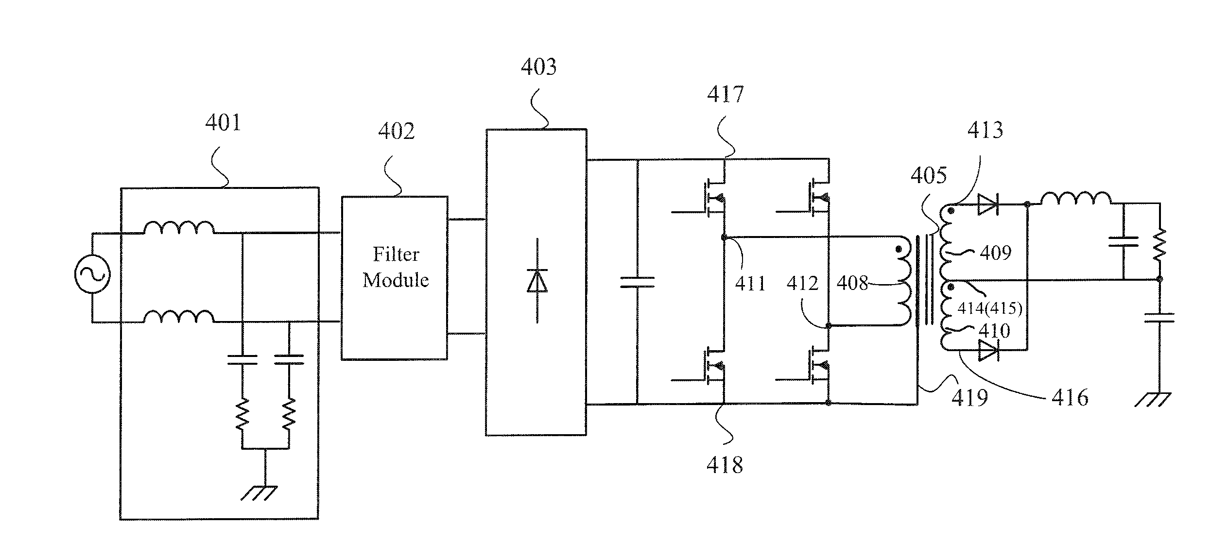
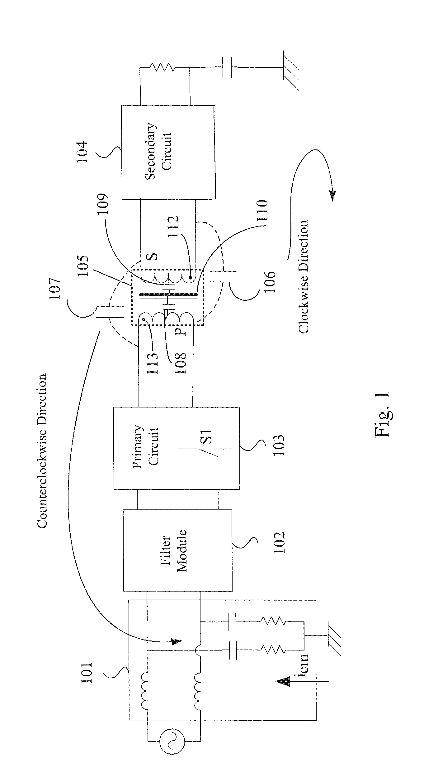
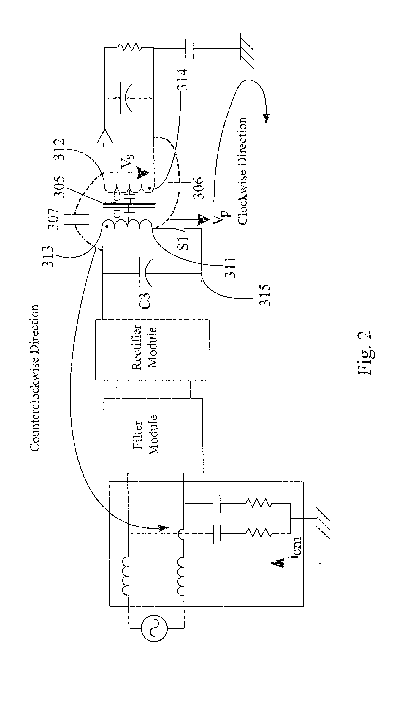
[0040]In order to make the technical contents of the present invention more detailed and more comprehensive, various embodiments of the present invention are described below with reference to the accompanying drawings. Wherever possible, the same reference numbers are used in the drawings and the description to refer to the same or like parts. However, those of ordinary skills in the art should understand that the embodiments described below are not used for limiting the scope of the present invention. Moreover, the accompanying drawings are only illustrative and are not made according to the original size.

[0041]In the embodiments of the present invention, the description relating to “coupled with / to” may refer to that a component is indirectly connected to another component through other components, and may also refer to that a component is directly connected to another component without using other components.

[0042]Specific implementations in various aspects of the present inventi...


PUM

PropertyMeasurementUnit
voltageaaaaaaaaaa
resistanceaaaaaaaaaa
inductanceaaaaaaaaaa

Abstract

A transformer capable of suppressing common mode current and a power converter thereof are provided. The transformer comprises a primary winding, a secondary winding, a magnet core and a shielding winding layer. The shielding winding layer has a first shielding winding and a second shielding winding. A voltage jump direction of the first shielding winding is constantly opposite to that of the second shielding winding. The shielding winding layer is coupled to a static terminal coupled with the primary winding or the secondary winding.

Description

RELATED APPLICATIONS[0001]This application claims priority to Chinese Application Serial Number 201210057664.2, filed Mar. 6, 2012, which is herein incorporated by reference in its entirety.BACKGROUND[0002]1. Field of Invention[0003]The present invention relates to a power converter. More particularly, the present invention relates to a transformer structure of the power converter capable of suppressing a common mode current.[0004]2. Description of Related Art[0005]In the prior art, a power converter including a transformer often causes a common mode noise. It is well known that, the transformer includes a primary winding, a magnet core and a secondary winding. In general, parasitic capacitances exist between the primary winding and the secondary winding, between the primary winding and the magnet core, and between the secondary winding and the magnet core. During the operation of the power converter, when a power component is repeatedly turned on or off at a high frequency, a volta...

Claims


Application Information

Patent Timeline
Patent Type & Authority Applications(United States)
IPC IPC(8): H02M3/335H01F27/36
CPCH02M3/335H02M2001/123H01F27/362H01F27/2885H01F27/2823H01F27/36H02M1/123H01F27/363
Inventor ZHOU, JIN-PINGXIE, YI-CONGYING, JIAN-PING
Owner DELTA ELECTRONICS SHANGHAI CO LTD
Why Eureka
Try Eureka