Optical pulse delay generator
- Summary
- Abstract
- Description
- Claims
- Application Information
AI Technical Summary
Benefits of technology
Problems solved by technology
Method used
Image
Examples
Embodiment Construction
[0048]The preferred embodiments of the present invention will be best understood by reference to the drawings, wherein identical or comparable parts are designated by the same reference signs throughout.
[0049]It will be readily understood that the present invention, as generally described herein, could vary in a wide range. Thus, the following more detailed description of the exemplary embodiments of the present invention, is not intended to limit the scope of the invention, as claimed, but is merely representative of presently preferred embodiments of the invention.
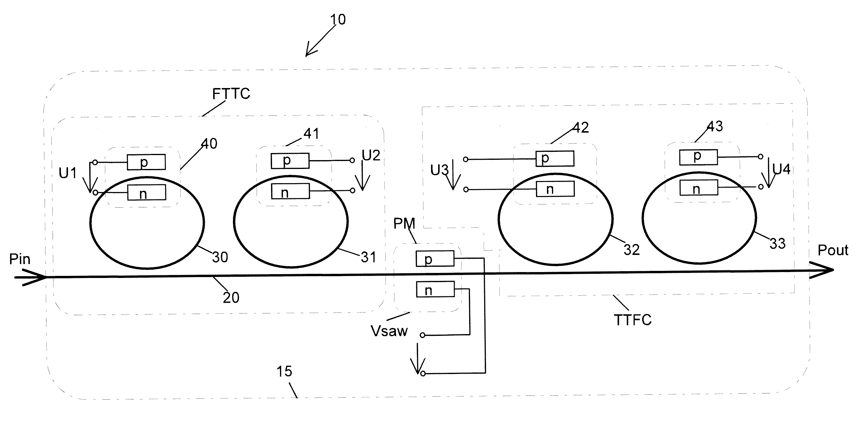
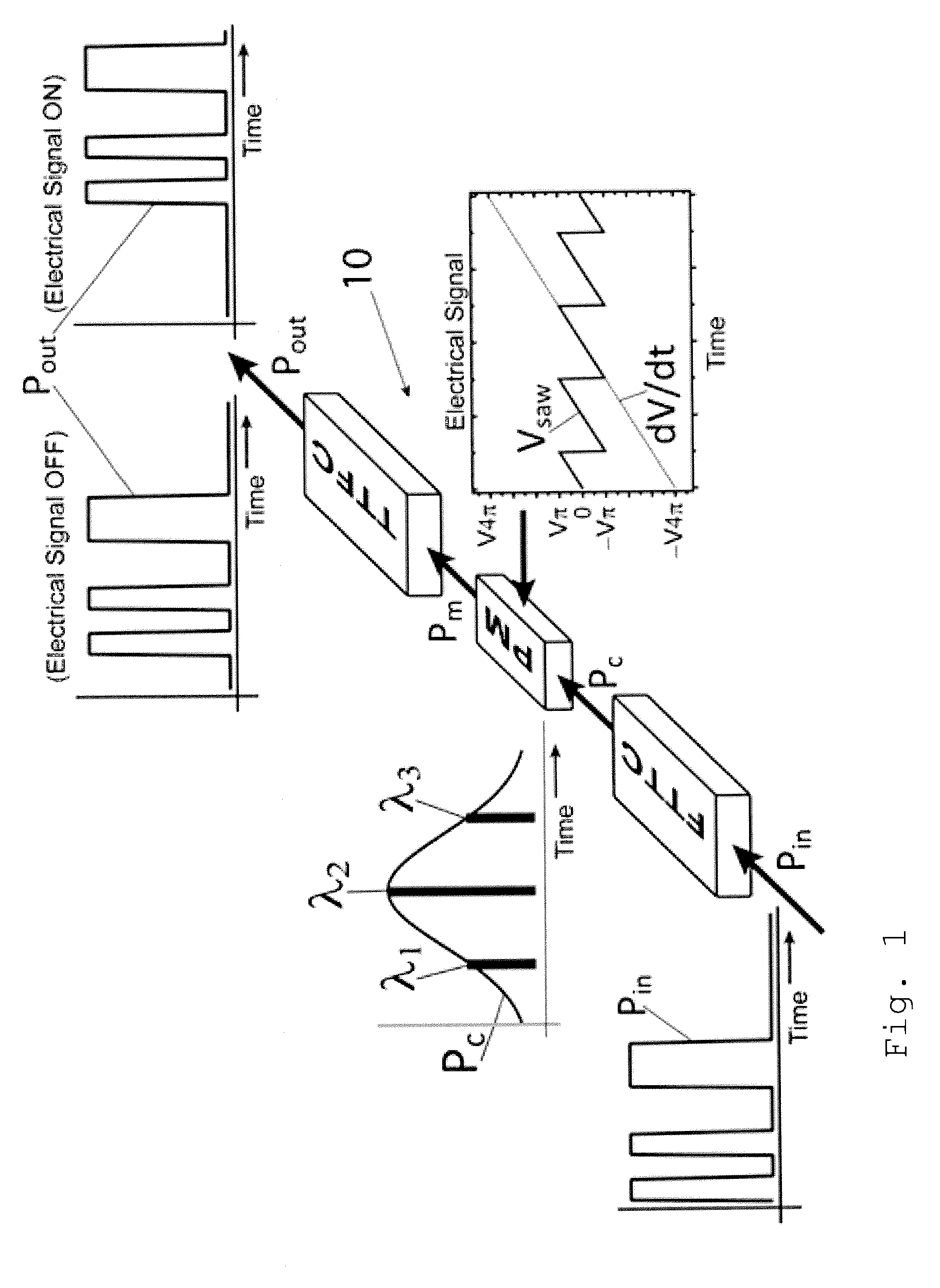
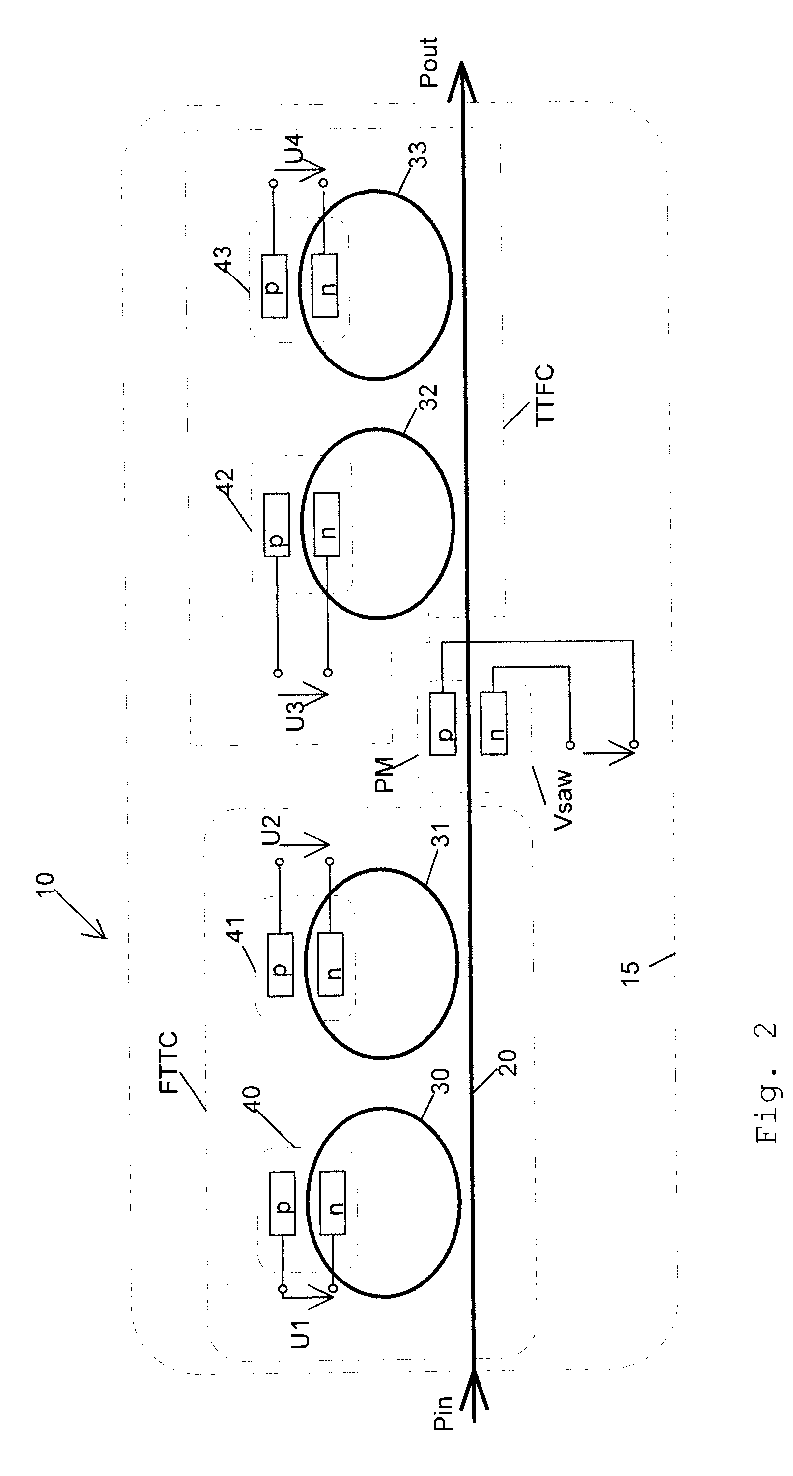
[0050]FIG. 1 shows a three-dimensional schematic view of an exemplary embodiment of an optical pulse delay generator 10 for delaying an incoming optical pulse Pin and generating a delayed optical output pulse Pout.
[0051]The delay generator 10 comprises a first optical converter FTTC. The first optical converter FTTC is a frequency-to-time conversion element, which is dispersive and separates the spectral components of th...
PUM
 Abstract
Description
Claims
Application Information
 - R&D
- Intellectual Property
- Life Sciences
- Materials
- Tech Scout
- Unparalleled Data Quality
- Higher Quality Content
- 60% Fewer Hallucinations
Browse by: Latest US Patents, China's latest patents, Technical Efficacy Thesaurus, Application Domain, Technology Topic, Popular Technical Reports.
© 2025 PatSnap. All rights reserved.Legal|Privacy policy|Modern Slavery Act Transparency Statement|Sitemap|About US| Contact US: help@patsnap.com


