Cutting insert

a cutting edge and insert technology, applied in the field of cutting inserts, can solve the problems of low machinability and decrease the tool life, and achieve the effects of preventing fracturing and chipping of the cutting edge, reducing the occurrence of burrs, and improving the sharpness of the cutting edg

Active Publication Date: 2013-09-12
MITSUBISHI MATERIALS CORP
View PDF1 Cites 18 Cited by
  • Summary
  • Abstract
  • Description
  • Claims
  • Application Information

AI Technical Summary

Benefits of technology

[0017]As described so far, according to the present invention, it is possible to prevent the fracturing and chipping of the cutting edge on light cutting of a difficult-to-cut material such as stainless steel and also improve sharpness of the cutting edge at a cutting boundary to suppress the occurrence of burrs. It is also possible to prevent abnormal wear and perform a stable and efficient turning process.

Problems solved by technology

Patent Document 1 has described such a problem that burrs will occur easily upon cutting these difficult-to-cut materials such as stainless steel, these burrs undergo work hardening to result in extremely low machinability and, therefore, a cutting edge of a cutting boundary which is exposed to the burrs is increased in chipping to fracture the cutting edge or greatly decrease the tool life due to what is called abnormal wear.

Method used


Image

  • Cutting insert
  • Cutting insert
  • Cutting insert

Examples


examples

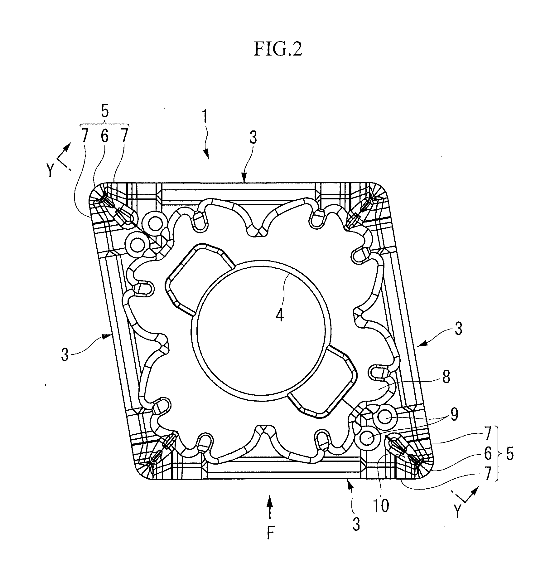
[0070]Next, a range in which the third region C is positioned will be demonstrated for its effect by referring to an example. In the present example, six types of cutting inserts were manufactured according to the above described embodiment in which changing a range where the third region C was positioned in a direction from the tangent line J orthogonal to the extension line I of the linear section 7 to the corner section 6 and in contact with the corner section 6 and along the extension line I. These cutting inserts are referred to as examples 1 to 6.

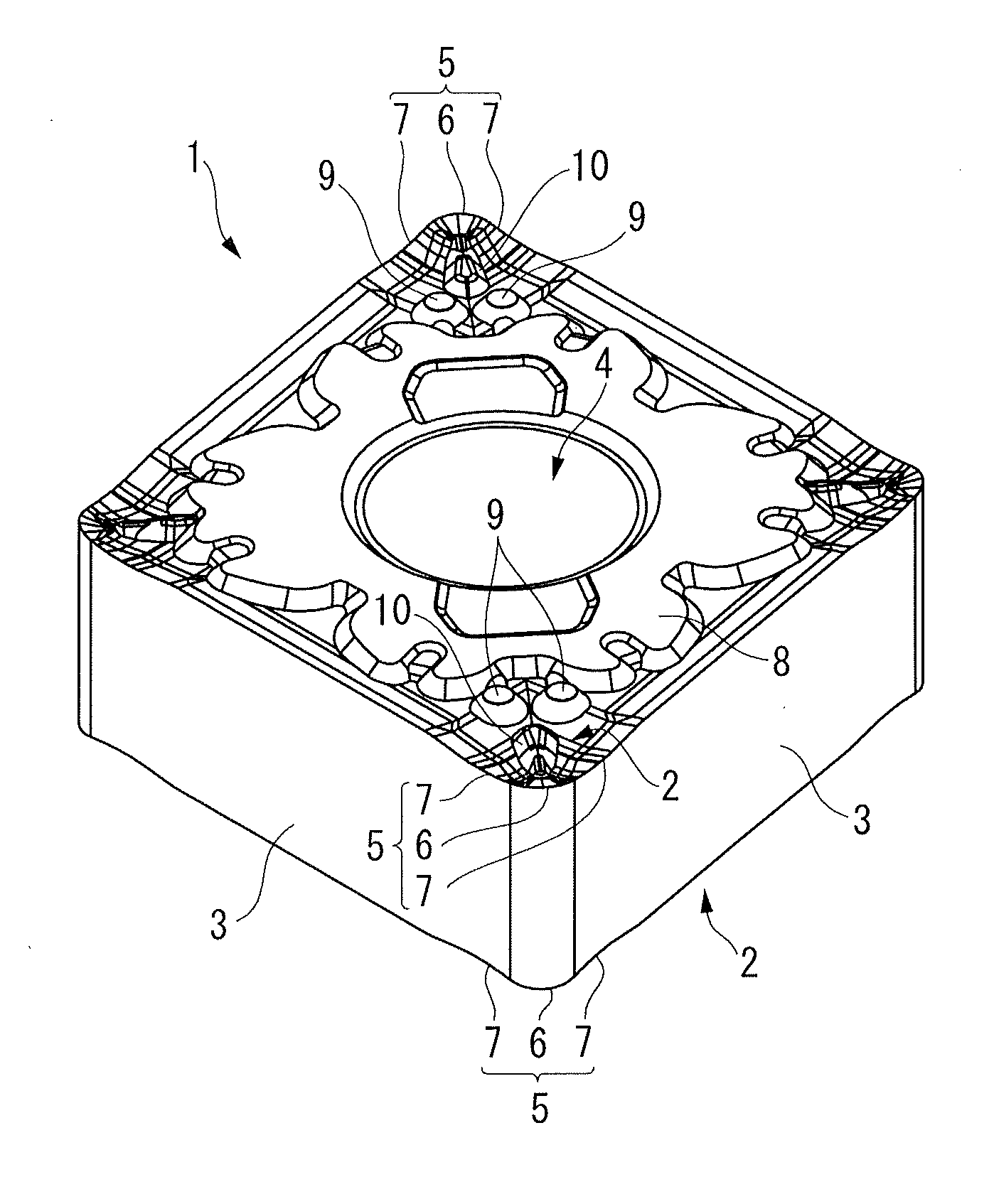
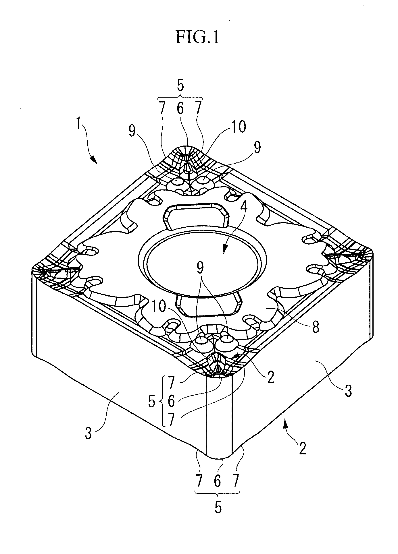
[0071]In these cutting inserts of the examples 1 to 6, the model number was CNMG120408, the nominal radius of corner section 6 was 0.8 (mm) and the actually measured radius R was 0.794 (mm). As described above, the rake angle θ3 of the cutting edge 5 in the third region C was 20°, the rake angles θ1, ∂2 in the first region A and the second region B were to be constant and each of which was 15°. Further, the insert main body 1 was made...


PUM

PropertyMeasurementUnit
inclination angleaaaaaaaaaa
depth of cutaaaaaaaaaa

Abstract

The present invention relates to the cutting insert having a cutting edge which has a corner section that forms a convex arc shape when seen in a planar view from direction facing the rake face and a linear section that is in contact with the corner section at least at one end of the corner section and extends linearly. The cutting edge is provided with a first region along the corner section when seen in a planar a second region along the linear section and a third region between the first region and the second region. A rake angle of the cutting edge in the third region is made greater than rake angles of the cutting edges in the first region and the second region.

Description

TECHNICAL FIELD[0001]The present invention relates to a cutting insert which is appropriately used in light cutting for turning a difficult-to-cut material such as stainless steel.[0002]Priority is claimed on Japanese Patent Application No. 2010-254999 filed on Nov. 15, 2010 in Japan and Japanese Patent Application No, 2011-246397 filed on Nov. 10, 2011 in Japan, the content of which is incorporated herein by reference.BACKGROUND ART[0003]Patent Document 1 has described such a problem that burrs will occur easily upon cutting these difficult-to-cut materials such as stainless steel, these burrs undergo work hardening to result in extremely low machinability and, therefore, a cutting edge of a cutting boundary which is exposed to the burrs is increased in chipping to fracture the cutting edge or greatly decrease the tool life due to what is called abnormal wear.[0004]Therefore, Patent Document 1 proposes a cutting insert in which a cutting edge is formed substantially linearly at an ...

Claims


Application Information

Patent Timeline
Patent Type & Authority Applications(United States)
IPC IPC(8): B23B27/16
CPCB23B27/141B23B2200/0447B23B2200/081Y10T407/235B23B2200/242B23B2200/286B23B27/1607B23B2200/201B23B2200/0452B23B2200/085B23B2200/202B23B27/00B23B27/14
Inventor NADA, YUTAKAICHINOSEKI, OSAMU
Owner MITSUBISHI MATERIALS CORP
Why Eureka
Try Eureka