
Self-Tunneling Lead

a self-tunnel and lead technology, applied in the field of medical leads, can solve the problems of time-consuming and invasive implantation procedures

Active Publication Date: 2013-09-12
MEDTRONIC INC
View PDF5 Cites 69 Cited by
  • Summary
  • Abstract
  • Description
  • Claims
  • Application Information

AI Technical Summary

Benefits of technology

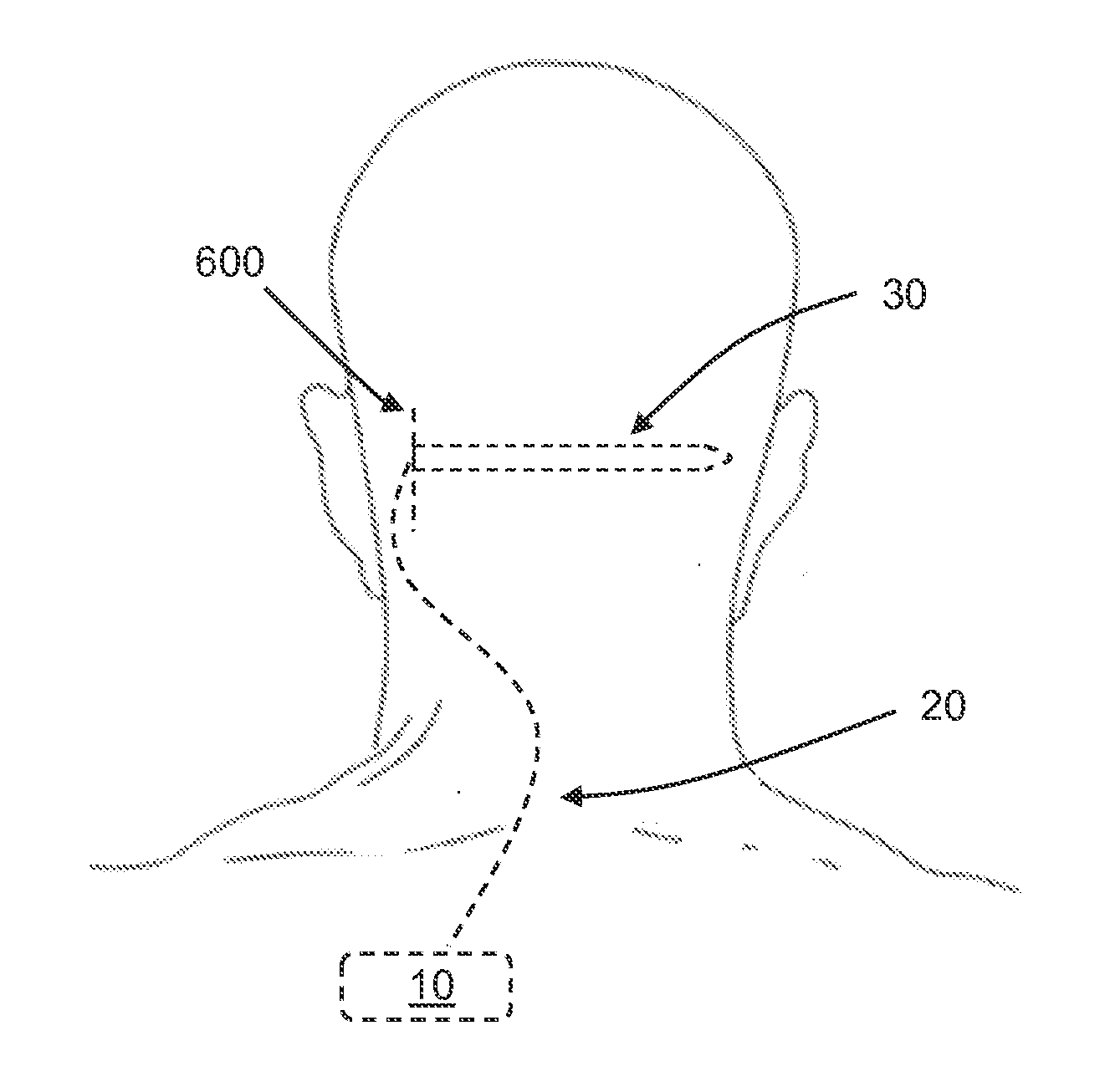
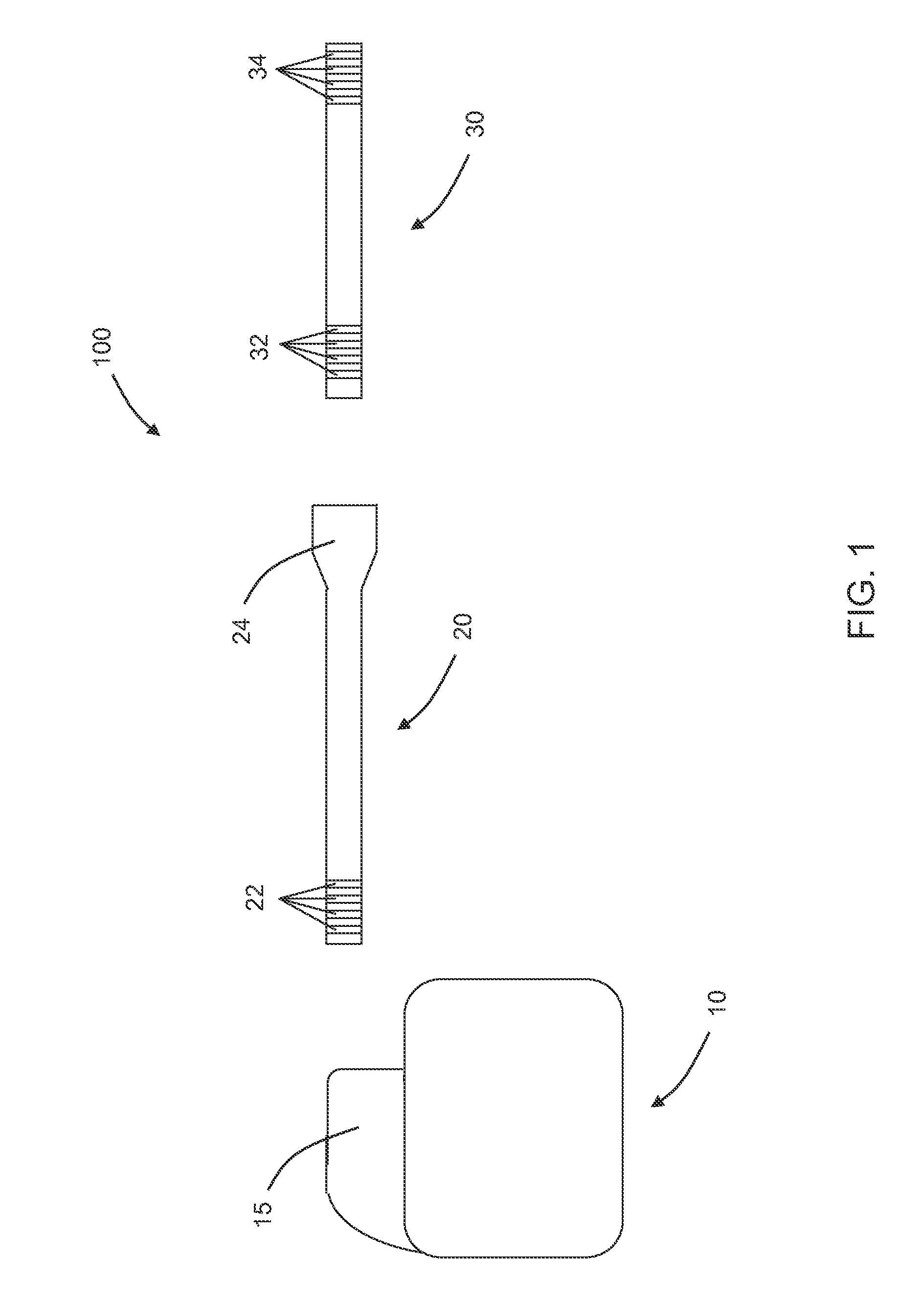
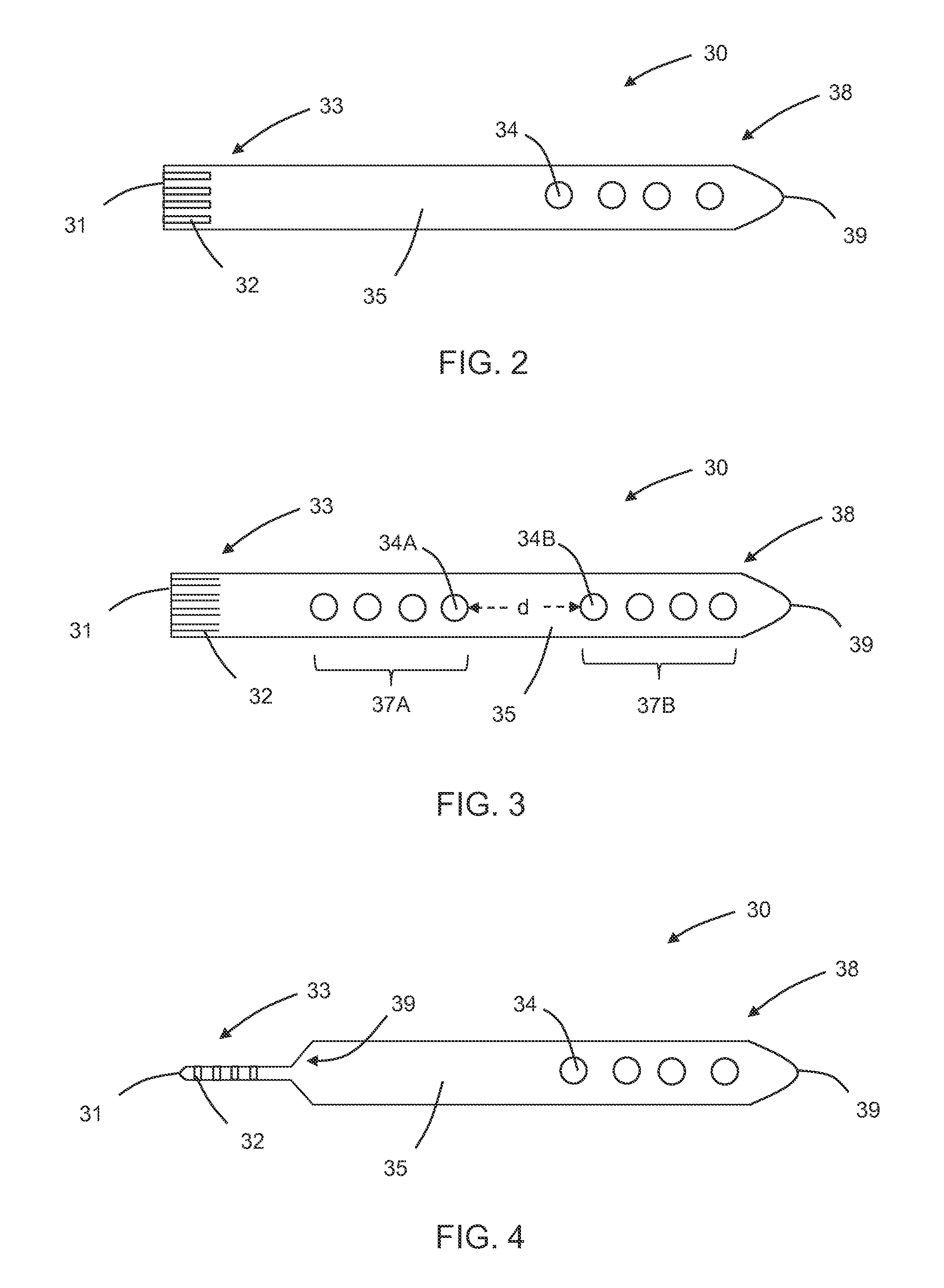
This patent describes leads that can be used for electrical stimulation therapies without the need for an introducer. The leads have a flat or planar distal end that is stiff enough to be pushed through subcutaneous tissue. The method involves advancing the lead through the tissue until the electrode is in the desired position. Overall, this patent provides an improved technique for inserting leads into the body for medical purposes.

Problems solved by technology

The lead implantation procedure can be time consuming and invasive.

Method used


Image

  • Self-Tunneling Lead
  • Self-Tunneling Lead
  • Self-Tunneling Lead

Examples


Embodiment Construction

[0019]In the following detailed description, reference is made to the accompanying drawings that form a part hereof, and in which are shown by way of illustration several specific embodiments of devices, systems and methods. It is to be understood that other embodiments are contemplated and may be made without departing from the scope or spirit of the present disclosure. The following detailed description, therefore, is not to be taken in a limiting sense.

[0020]All scientific and technical terms used herein have meanings commonly used in the art unless otherwise specified. The definitions provided herein are to facilitate understanding of certain terms used frequently herein and are not meant to limit the scope of the present disclosure.

[0021]As used in this specification and the appended claims, the singular forms “a”, “an”, and “the” encompass embodiments having plural referents, unless the content clearly dictates otherwise. As used in this specification and the appended claims, ...


PUM


Abstract

An implantable medical lead includes (i) a proximal end portion including a contact and having a proximal end; and (ii) a distal end portion including an electrode and having a distal end. The electrode is electrically coupled to the contact. The distal end portion is generally flat and sufficiently stiff to be pushed through subcutaneous tissue.

Description

FIELD[0001]The present disclosure relates to implantable medical devices; more particularly to medical leads capable of delivering electrical signals to tissue of a patient, such as a nerve.BACKGROUND[0002]Implantable medical systems that include an implantable electrical signal generator device and one or more implantable medical leads have been used to treat a variety of diseases and disorders, such as Parkinson's disease, essential tremor, obsessive-compulsive disorder, pain, nausea and vomiting, and incontinence. With such systems, the electrical signal generator device, often referred to as an implantable pulse generator or IPG, is implanted in subcutaneous tissue of a patient, such as in the abdomen, buttocks, chest, or the like, at a distance from the therapeutic target, such as the brain, spinal cord, gastrointestinal tract or the like. Leads carry electrical signals generated by the IPG to the therapeutic site once operably coupled to the IPG and properly positioned relativ...

Claims


Application Information

Patent Timeline
Patent Type & Authority Applications(United States)
IPC IPC(8): A61N1/05
CPCA61N1/0502A61N1/0504A61N1/0551
Inventor BAUDINO, MICHAEL D.
Owner MEDTRONIC INC
Learn More