
Electromagnetic Tracker (AC) with Extended Range and Distortion Compensation Capabilities Employing Multiple Transmitters

a technology of electromagnetic distortion compensation and tracker, which is applied in the direction of mechanical control devices, instruments, manual control with single controlling member, etc., can solve the problems of electromagnetic distortion sensitivity, inability to effectively compensate distortion, and inability to achieve distortion compensation

Active Publication Date: 2013-09-12
PENUMBRA
View PDF6 Cites 12 Cited by
  • Summary
  • Abstract
  • Description
  • Claims
  • Application Information

AI Technical Summary

Benefits of technology

This patent describes an apparatus and method for determining the position and orientation of an object in a common reference frame despite the presence of electromagnetic distortion. The apparatus includes two or more transmitters, a sensor attached to the object, and a signal processor. The transmitters generate an alternating current electromagnetic field and the sensor measures the induced current from each transmitter. The signal processor calculates a transfer function between each transmitter and the sensor and uses this function to determine the position and orientation of the object in the reference frame. The method also includes performing distortion compensation to estimate the effect of electromagnetic distortion and then removing it to provide a common position and orientation solution for the sensor. Overall, this technology allows for precise position and orientation determination in the presence of electromagnetic distortion.

Problems solved by technology

However, as is known in the art, one problem of AC electromagnetic trackers is their sensitivity to electromagnetic distortion caused by eddy currents induced by the magnetic field of the transmitter / source in conducting surfaces existing within the operating volume.
However, these trackers have no effective mechanism for the distortion compensation and their performance is limited by the factors described above.
Another known prior approach is described in U.S. Pat. No. 6,539,327 which offers the use of a gradient field for reliable tracking but due to exactly this factor has significantly limited spatial performance in comparison with “conventional” AC trackers.
However, these trackers become more complex from the point of view of hardware and firmware and, while providing additional reference, still have the limitations described earlier.
For example, combination electromagnetic / optical trackers will not compensate for the distortion or extend an operational range if optical line of sight is obstructed.
Yet this system has no provision for real time distortion compensation and has limited range.

Method used


Image

  • Electromagnetic Tracker (AC) with Extended Range and Distortion Compensation Capabilities Employing Multiple Transmitters
  • Electromagnetic Tracker (AC) with Extended Range and Distortion Compensation Capabilities Employing Multiple Transmitters
  • Electromagnetic Tracker (AC) with Extended Range and Distortion Compensation Capabilities Employing Multiple Transmitters

Examples


Embodiment Construction

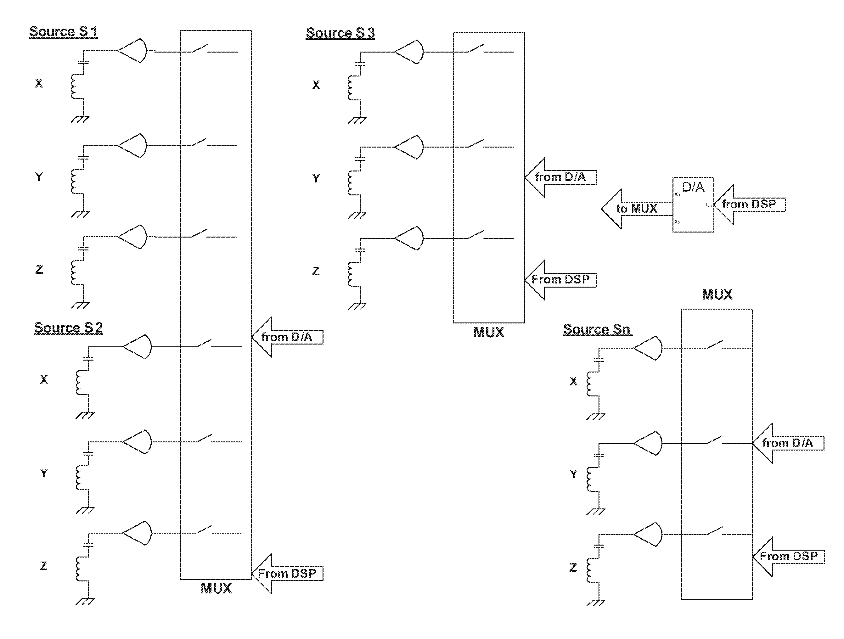
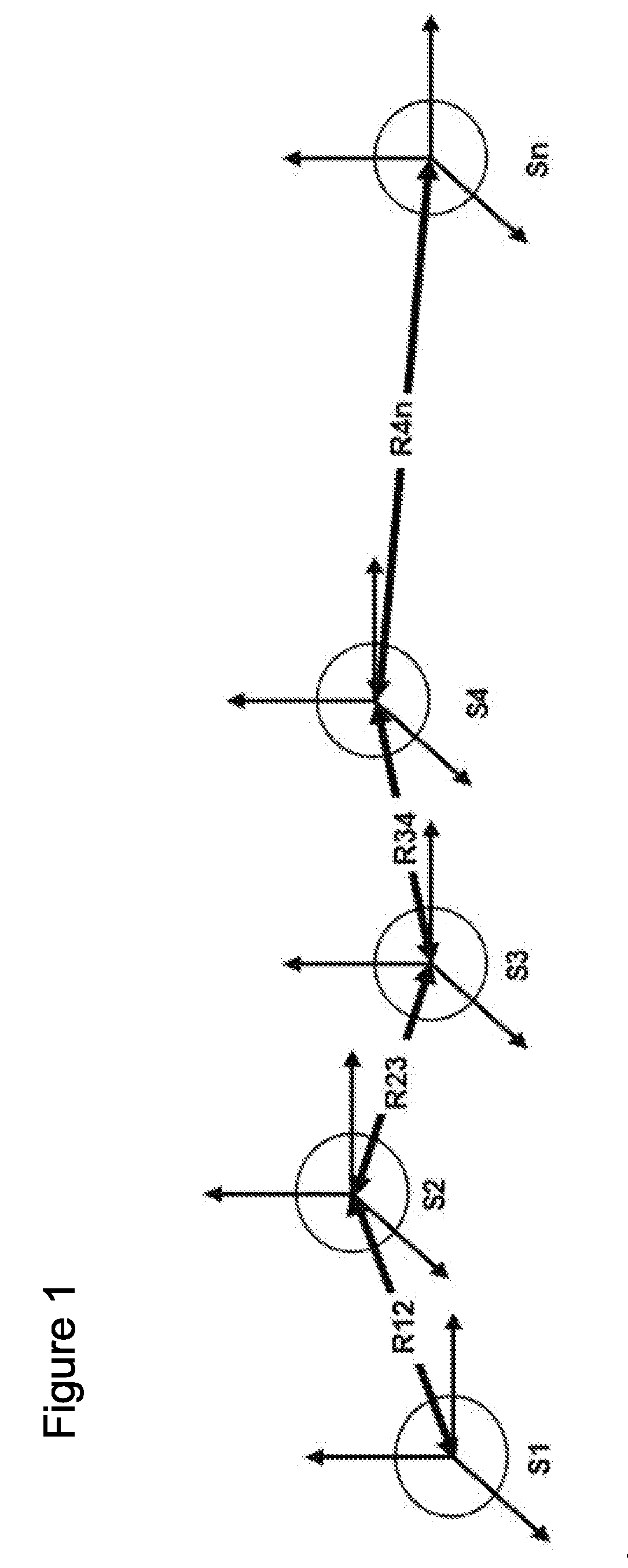
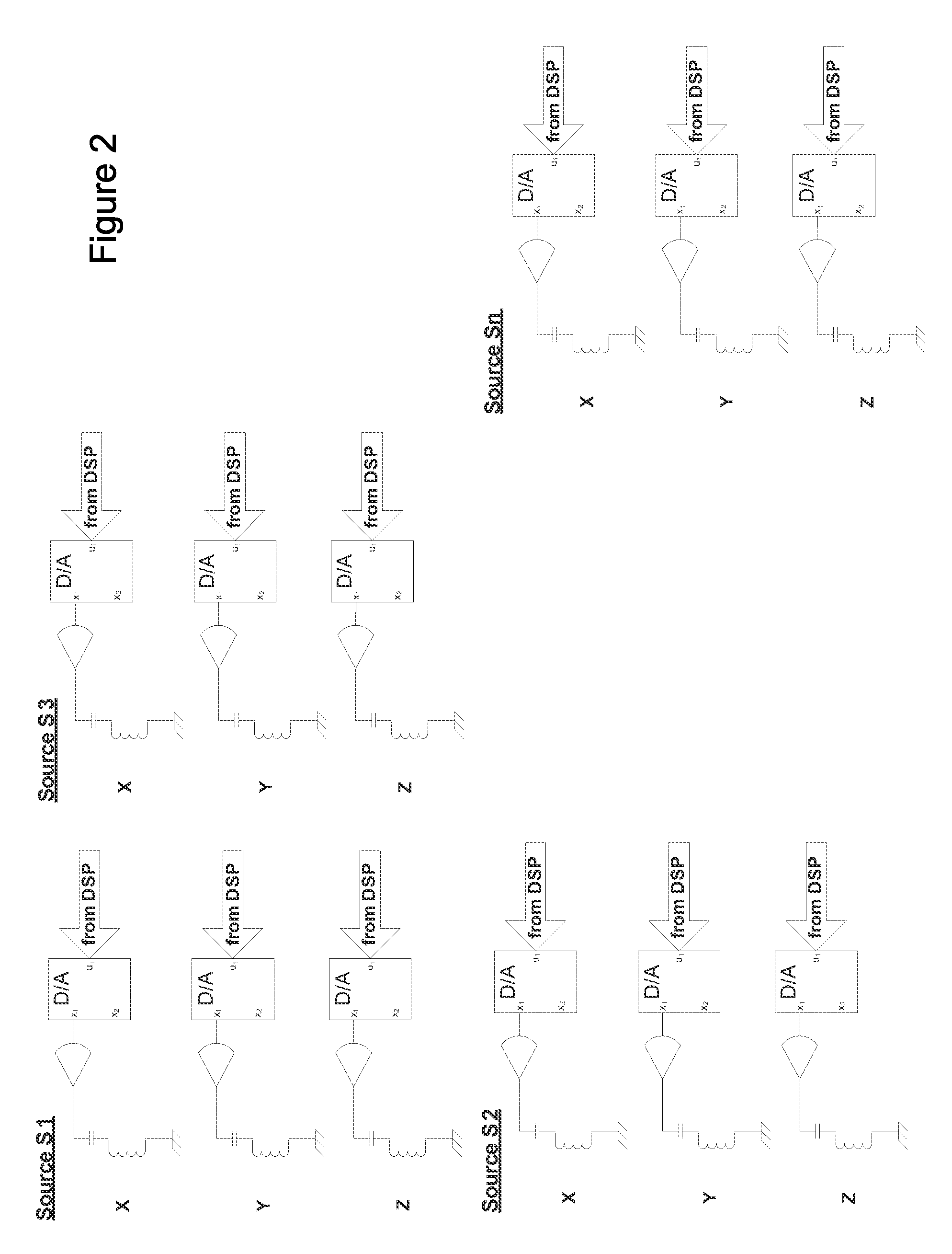
[0026]Described herein is an AC electromagnetic tracker system with increased operational range and an ability to compensate for electromagnetic distortion in the local operating environment. The system uses multiple “N” sources / transmitters, each of which contains 3 non-coplanar coils for generating a magnetic field. As is understood by one of skill in the art, N sources are equivalent to increasing an effective area of a single transmitter N times, i.e., term Ssource in the above equations (1 and 2) is replaced by N*Ssource, thereby increasing operational range.

[0027]In one embodiment, the relative position and orientation of the N sources are known and constant at a time in a common reference frame.

[0028]The tracker sensor in the local operating environment receives the generated signal of each of the N sources and, using known processing components and physical configurations such as amplifiers, analog-to-digital converters (ADCs), processor elements and wired or wireless commun...


PUM


Abstract

An alternating current (AC) electromagnetic tracker system with increased operational range and an ability to compensate for electromagnetic distortion in the local operating environment. The system uses multiple “N” sources / transmitters located at known positions in a common reference frame. A sensor receives the generated signal of each of the sources and a processor computes a position and orientation of the sensor from each. The processor further uses the known relative position and orientation between the N sources to compensate for distortion in the operating environment.

Description

CROSS-REFERENCE TO RELATED APPLICATIONS[0001]This application claims the benefit of U.S. Provisional Patent Application No. 61 / 609,516 filed on Mar. 12, 2012 and entitled “Electromagnetic Tracker (AC) with Extended Range and Distortion Compensation Capabilities Employing Multiple Transmitters,” which is incorporated herein by reference in its entirety.BACKGROUND[0002]1. Field of the Invention[0003]The field of this invention is in the area of computer input devices, including video game controllers.[0004]2. Related Art[0005]As the market for and variety of video games has increased, so has the demand for video game controllers. Early controllers were typically joysticks or trackballs in a fixed mount thus requiring the user or game player to remain fairly stationary while playing the video game. Seeking to give the game player more freedom of movement as well as a greater range of video game input control, still later controllers were handheld and incorporated accelerometers to dete...

Claims


Application Information

Patent Timeline
IPC IPC(8): G01D18/00G06F17/10
CPCG01D18/00G05G9/00G01D5/208G06F17/10
Inventor KHALFIN, IGORRUBIN, AMIR
Owner PENUMBRA
Learn More