
Secure tunneling platform system and method

a tunneling platform and tunneling technology, applied in the field of network bandwidth sharing, can solve the problems of reducing the number of ip addresses and the ability of the isp to detect only one ip address, and achieve the effect of less complex and less interferen

Active Publication Date: 2013-09-12
FON WIRELESS
View PDF11 Cites 16 Cited by
  • Summary
  • Abstract
  • Description
  • Claims
  • Application Information

AI Technical Summary

Benefits of technology

[0015]Although many of the examples herein relate to IP conservation, embodiments that do not provide or otherwise support NAT translation to support a limited or otherwise reduced number of IP addresses may be less complex and expensive by simply assigning independent public IP addresses to users connected at any given time, instead of translating private IP addresses via NAT and sharing one or more public IP addresses.
[0016]In addition, the infrastructure in an embodiment provides substantial availability as a function of redundancy for, for example, datacenter and communication providers. Substantial scalability is also supported, for example, to support hundreds off thousands of concurrent users by adding network equipment that, for example, terminates the tunnels with Configured routers. In case of a lower number of concurrent users, the system is adjustable, as well as platform costs, to scale appropriately in terms of functionality and cost.
[0032]The present application is further described and illustrated in connection with accompanying Appendix A and Appendix B, the entire contents of which are hereby incorporated by reference. In Appendix B, for example, PPPoE technology is substituted for PPP and L2TP. Moreover, a single customer provided equipment from an ISP (e.g., “CPE”) device is substituted for a combination of a second router device (e.g., a “Fonera” device) and a “CPE.” This embodiment is more efficient and less costly, for example, due to a reduction in equipment.

Problems solved by technology

Unfortunately, the ISP can only detect the one IP address that is shared by and accessed both users.
Although many of the examples herein relate to IP conservation, embodiments that do not provide or otherwise support NAT translation to support a limited or otherwise reduced number of IP addresses may be less complex and expensive by simply assigning independent public IP addresses to users connected at any given time, instead of translating private IP addresses via NAT and sharing one or more public IP addresses.

Method used


Image

  • Secure tunneling platform system and method
  • Secure tunneling platform system and method
  • Secure tunneling platform system and method

Examples


Embodiment Construction

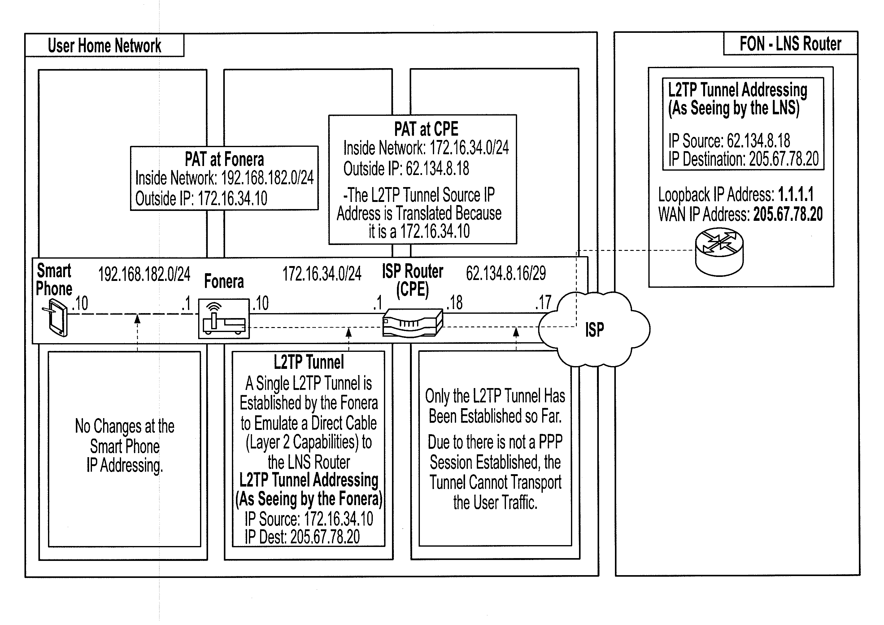
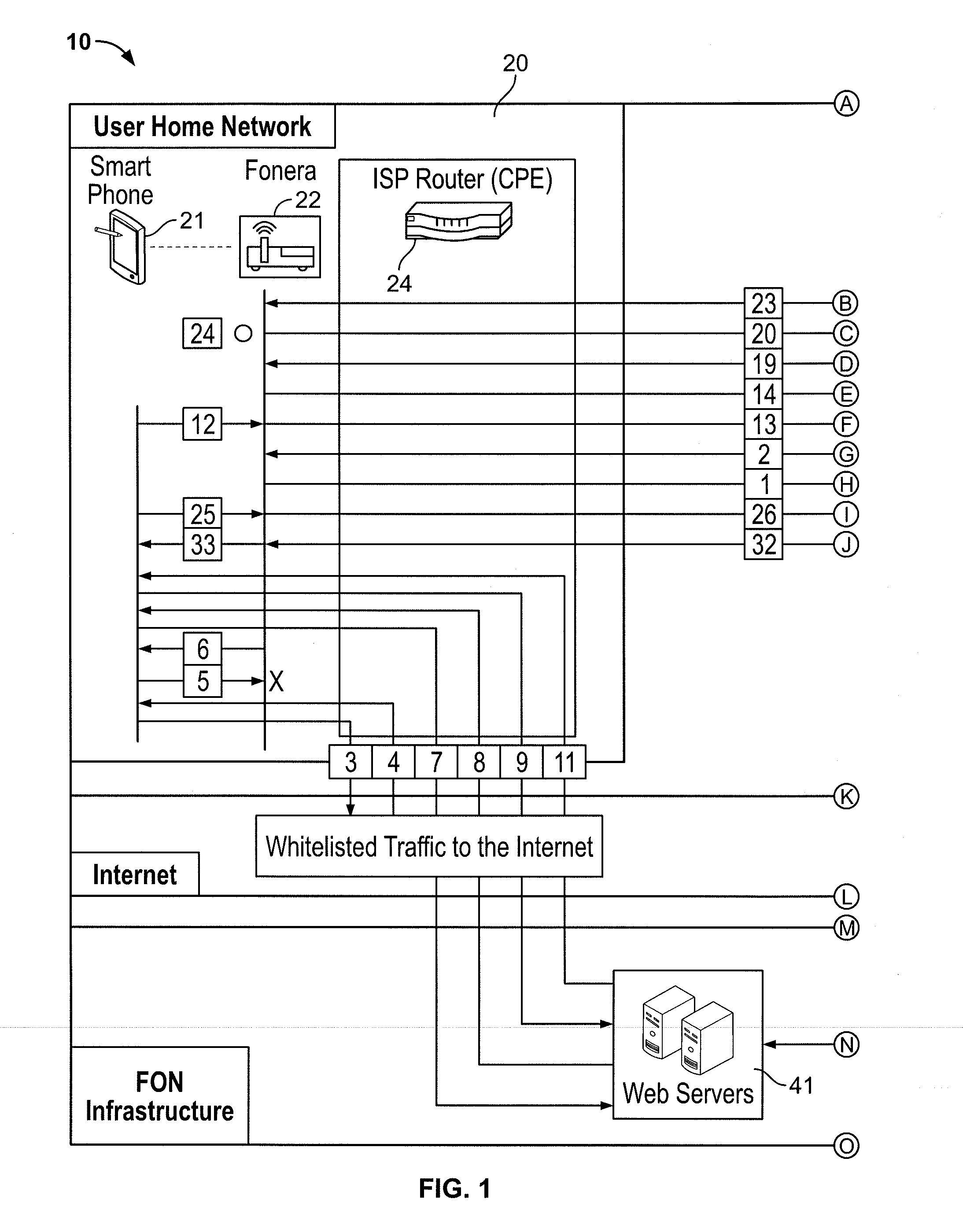
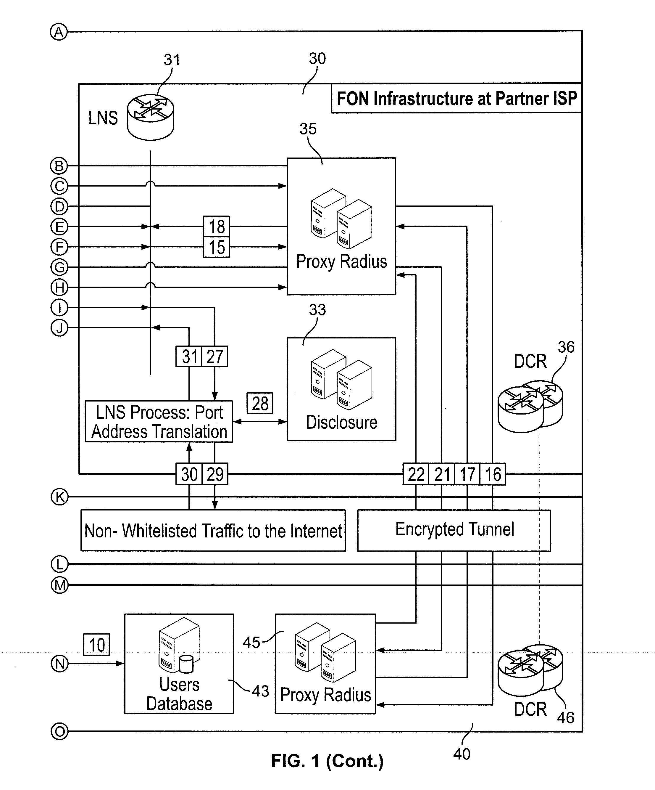
[0053]An example of a user connection flow of tunnel authorization, user identification and access through the layer 2 tunneling protocol network server (LNS) will now be described with reference to FIG. 1 and FIG. 10. A configured router 22, such as a wireless router, may be positioned in a user's home or office so as to provide access to a user's device, such as a smart phone, laptop, desktop or other type of handheld device 21. While described herein as a wireless router 22, it will be understood that a wired connection may also be provided. Further, more than one such user device 21 may share the same connection to the internet via wireless router 22. Similarly, more than one device may share the connection through ISP router 24, indicated in FIG. 1 as ISP Router CPE (Customer Premises Equipment), which also may be provided at the user's premises 20.

[0054]Using the browser of the user device 21, user attempts to connect to the internet through wireless router 22 as illustrated b...


PUM


Abstract

A system identifies a user, even a user behind a wireless router, and provides a virtual tunnel over the internet for communication with the user. A data center at an Internet Service Provider may work in concert with a central data center to authenticate the user and to provide access, for example using a layer 2 tunneling protocol and a point-to-point data (PPP) link protocol. A layer 2 tunneling protocol network server (LNS) may provide public IP address translation services.

Description

CROSS REFERENCE TO RELATED APPLICATIONS[0001]The present application claims priority to U.S. Provisional Patent Application No. 61 / 559,460, filed Nov. 14, 2011. The present application is also a Continuation Application of U.S. application Ser. No. 13 / 339,807, filed Dec. 29, 2011, which claims priority to U.S. Provisional Application No. 61 / 559,460, filed Nov. 14, 2011 and U.S. Provisional Patent Application No. 61 / 428,620, filed Dec. 30, 2010, the entire contents of, all of which are incorporated by reference herein.BACKGROUND[0002]1. Field of the Disclosure[0003]The present application relates, generally, to network bandwidth sharing and, more particular, to secure tunneling and to identifying users.[0004]2. Related Art[0005]Sharing bandwidth, such as via Wi-Fi, is a practical solution that has benefits such as described in commonly assigned U.S. Pat. No. 7,924,780 issued Apr. 12, 2011, the entire contents of which is incorporated herein by reference. Users who access communicatio...

Claims


Application Information

Patent Timeline
Patent Type & Authority Applications(United States)
IPC IPC(8): H04L29/06
CPCH04L29/12367H04L61/2514H04L63/1425H04L63/083H04L63/30H04W12/06H04L63/162H04W12/068
Inventor VARSAVSKY WAISMAN-DIAMOND, MARTINBECARES FERNANDEZ, GONZALO JULIANARGINZONIZ CEBREIRO, XABIER IURGIMUNOZ CASTRO, JUAN MANUELMEDRANO, PABLO MARTIN
Owner FON WIRELESS
Learn More