
Optical module and scanning image display device

Inactive Publication Date: 2013-09-19
HITACHI MEDIA ELECTORONICS CO LTD
View PDF6 Cites 26 Cited by
  • Summary
  • Abstract
  • Description
  • Claims
  • Application Information

AI Technical Summary

Benefits of technology

The present invention provides a compact optical module with heating and cooling devices for setting the temperatures of lasers to be within the guaranteed operating temperature range of the lasers, which can suppress a relative positional displacement of each spot on a display region such as a screen, and a scanning image display device. This ensures that the lasers operate within their optimal temperature range, reducing the risk of malfunctions and image quality issues. Additionally, the invention can adjust the temperatures of lasers to inhibit relative positional displacements of laser spots on a display region, such as a screen, even if the ambient temperature range is wider than the guaranteed operating temperature range of the lasers.

Problems solved by technology

If the optical axes are misaligned, a problem would arise that relative positional displacements of spots of the respective colors are generated on a display region such as a screen, so that a resulting image becomes blurred.
In addition, when using a scanning image display device, there is a problem in that it is necessary to take into consideration deviations of the optical axes due to a possible positional displacement of an optical component resulting from heat deformation.
Meanwhile, when the operating temperature of a laser is outside the guaranteed operating temperature range of the laser, a difference in the visibility of each color would be generated due to a temperature-dependent laser wavelength fluctuation, so that a color deviation of the image would occur such that the entire screen becomes reddish, or the laser output would decrease or the operating life of the laser would shorten.
Thus, an optical module for a case where the ambient temperature range is wider than the guaranteed operating temperature range of lasers such as a head-up display mounted on a vehicle or the like has a problem in that heating and cooling devices are needed for adjusting the temperatures of the lasers to be within the guaranteed operating temperature range of the lasers.
However, in the conventional art, the following problem with an optical module for a case where the ambient temperature range is wider than the guaranteed operating temperature range of lasers is not taken into consideration.

Method used


Image

  • Optical module and scanning image display device
  • Optical module and scanning image display device
  • Optical module and scanning image display device

Examples


embodiment 1

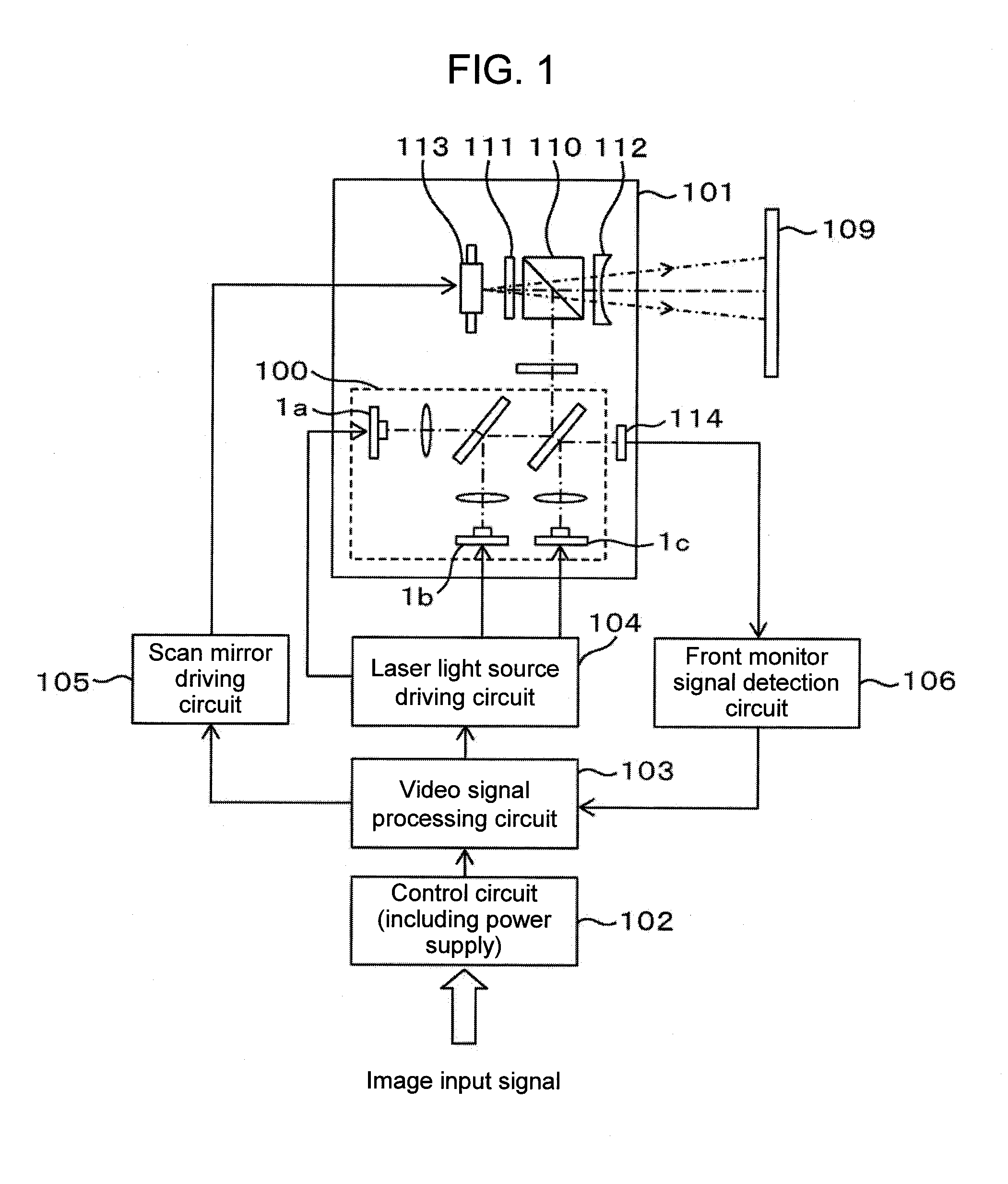
[0041]FIG. 1 is a configuration diagram of a scanning image display device in accordance with an embodiment of the present invention. In FIG. 1, an optical module 101 includes a laser light source module 100 having a first laser 1a, a second laser 1b, and a third laser 1c, which are laser light sources corresponding to the three colors of read (R), green (G), and blue (B), respectively, and a beam coupling unit that couples together light beams emitted from the respective laser light sources; a projection unit that projects the coupled light beam onto a screen 109; and a scan unit that allows a projection light beam to be two-dimensionally scanned on the screen 109. The projection unit includes a polarizing beam splitter (PBS) 110, a quarter-wave plate 111, an angle-of-view widening element 112, and the like. In addition, the scan unit includes a scan mirror 113 and the like.

[0042]An image signal to be displayed is input to a video signal processing circuit 103 via a control circuit...

embodiment 2

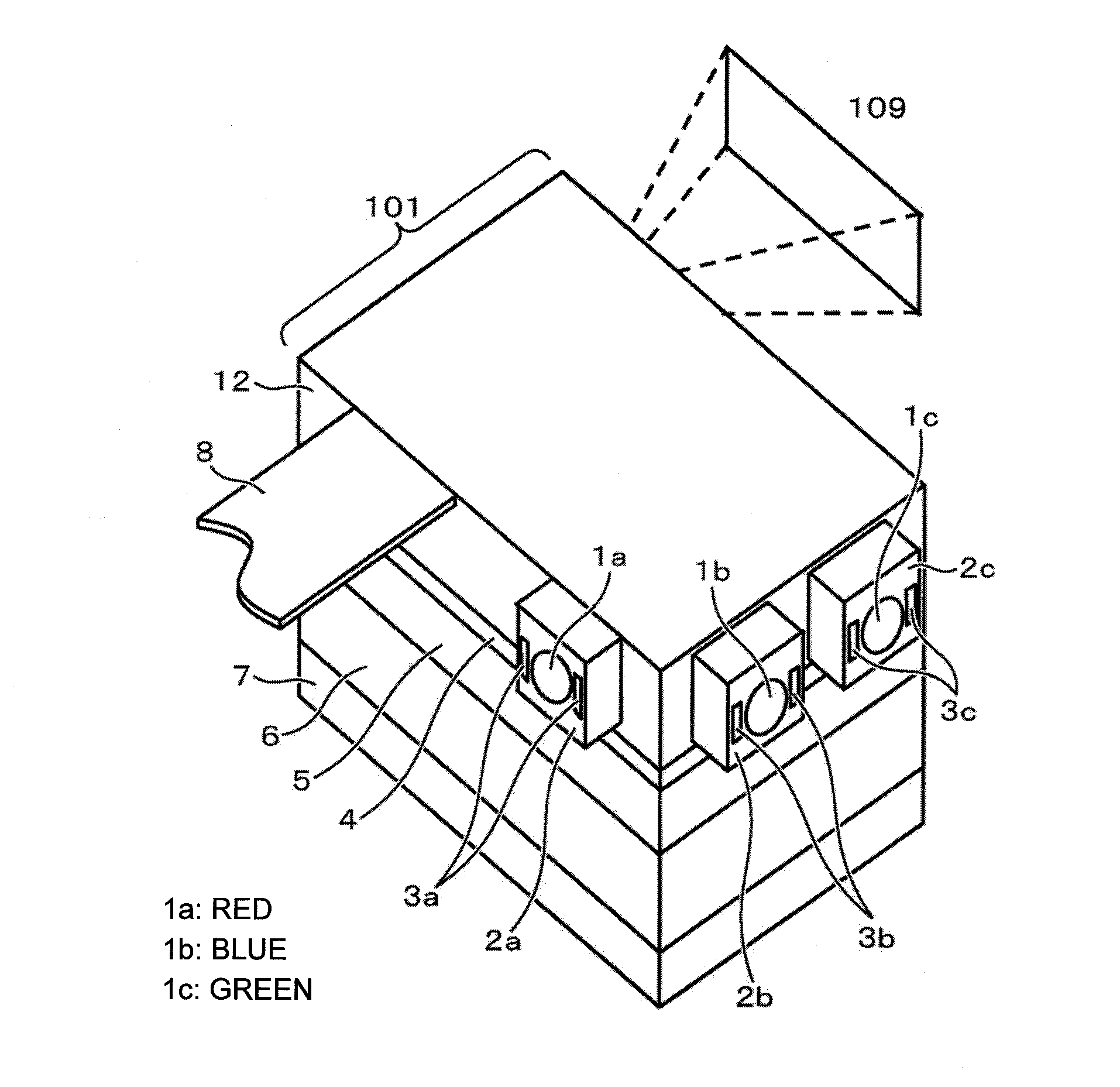
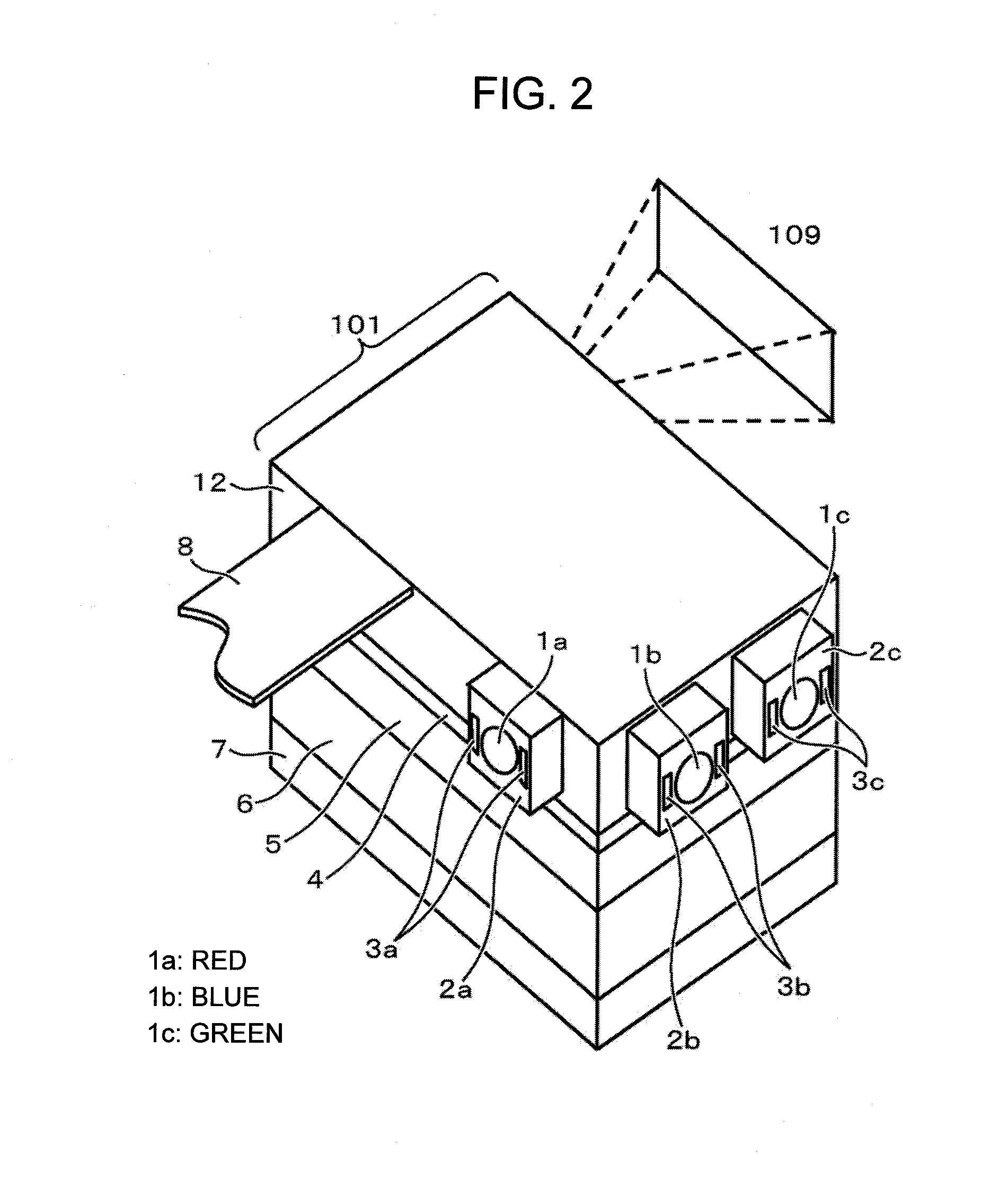
[0063]FIG. 6 is a perspective view showing a second embodiment of the optical module in accordance with this embodiment. In FIG. 6, a heat spreader 11 is arranged on the lower surface or the upper surface of the optical module 101 with interposed therebetween thermally-conducive grease 4, a thermally conductive sheet, or a thermally conductive gel. Then, the heat spreader 11 is extended on a horizontal plane in the direction of the second laser 1b and the third laser 1c away from the case 12 when seen from the case 12 so that the heat spreader 11 is connected to a cooling element 5 arranged next to the second laser 1b and the third laser 1c of the optical module 101, whereby the optical module 101 can be cooled. When such an arrangement is used, the cooling element 5 and a heat dissipation fin 6 and a fan 7 for the cooling element can be arranged in the height direction of the optical module 101. Thus, a reduction in thickness of the device is possible.

[0064]The first heating elemen...

embodiment 3

[0067]FIG. 7 is a perspective view showing a third embodiment of the optical module in accordance with this embodiment. In FIG. 7, as the arrangement of optical components, when a green laser is arranged as the first laser 1a, a red laser is arranged as the second laser 1b, and a blue laser is arranged as the third laser 1c for convenience of the optical properties, a heat spreader 11 is arranged on the lower surface or the upper surface of the optical module 101 as in the second embodiment, and the heat spreader 11 is extended in a horizontal plane in the direction of the first laser 1a and the second laser 1b away from the case 12 when seen from the case 12 so that the heat spreader 11 is connected to a cooling element 5 arranged next to and interposed between the first laser 1a and the second laser 1b of the optical module 101, whereby the temperature distribution of the optical module 101 can be made uniform. According to such a component arrangement, it is possible to suppress ...


PUM


Abstract

In an optical module that aligns light beams from lasers of the three colors of red, green, and blue along a single combined beam optical axis, when the ambient temperature range is wider than the guaranteed operating range of the lasers, relative positional displacements of beam spots of the three colors that are generated due to a displacement or a deformation resulting from a temperature range at a heating time or a cooling time are suppressed. The optical module, which has mounted thereon a plurality of lasers, and emits light beams from the plurality of lasers, includes a cooling device that cools the entire optical module via a case on which the optical module is mounted, and heating devices that are provided on respective laser holders and individually heat the respective lasers.

Description

BACKGROUND[0001]1. Technical Field[0002]The present invention relates to an optical module and a scanning image display device. For example, the present invention relates to an optical module that emits light beams from a plurality of lasers so as to align the light beams along a single optical axis, and a scanning image display device that displays an image of the light beams from the optical module.[0003]2. Background Art[0004]In recent years, compact projectors that can be easily carried about and can display images on large screens have been actively developed. Compact projectors that can be connected to notebook PCs and the like and video cameras and the like having built-in projectors that can project recorded images are already available in the market. Thus, it is predicted that projectors built in portable phones or smart phones will also become available in future.[0005]As a scheme of projectors, a scheme of using a lamp, an LED, or the like for a light source and projectin...

Claims


Application Information

Patent Timeline
IPC IPC(8): G03B21/16F21V29/00
CPCG03B21/16F21V29/00G03B21/2033G03B33/12H04N9/3144H01S5/4093G02B7/008G02B27/104H04N9/3129H01S5/02453
Inventor KATO, SEIICHIKAZAMA, ATSUSHIAMANO, YASUOHOSAKA, NORIOKUROIWA, TSUTOMUTANAKA, TEPPEI
Owner HITACHI MEDIA ELECTORONICS CO LTD
Learn More