Advection Fan and An Impeller Thereof

a technology of advection fan and impeller, which is applied in the direction of valve construction, piston pumps, marine propulsion, etc., can solve the problems of inability to efficiently reduce the height of the impeller of the advection fan, the inability of the blower fan to be applied to electronic devices that draw air in the radial direction, and the inability to apply the blower fan to electronic devices such as handsets or personal digital assistants (pda), so as to

Inactive Publication Date: 2013-09-19
SUNONWEALTH ELECTRIC MACHINE IND
View PDF2 Cites 15 Cited by
  • Summary
  • Abstract
  • Description
  • Claims
  • Application Information

AI Technical Summary

Benefits of technology

[0014]It is therefore the objective of this invention to provide an advection fan capable of efficiently preventing the disr...

Problems solved by technology

As a result, the height of the electronic device cannot be reduced.
In addition, since the blower fan draws air via the axial air inlet (draws air in the axial direction) and expels air via the radial air outlet (expels air in the radial direction), the blower fan cannot be applied to electronic devices that draw air in the radial direction, such as a handset or a Personal Digital Assistant (PDA).
However, since the modern electronic devices usually have a miniature design, the height of the impeller of the advection fan must be efficiently reduced without affecting the air-driving capacity of the advection fan.
Although the thin im...

Method used


Image

  • Advection Fan and An Impeller Thereof
  • Advection Fan and An Impeller Thereof
  • Advection Fan and An Impeller Thereof

Examples


first embodiment

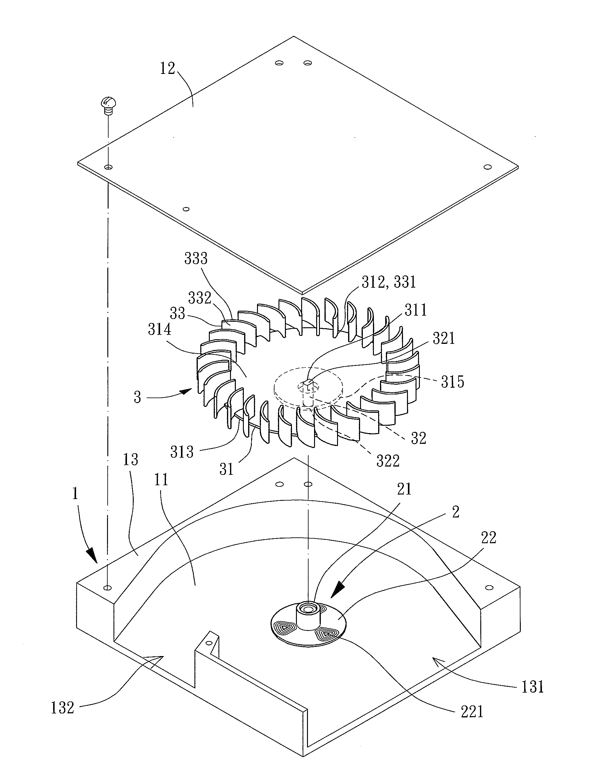
[0044]Referring to FIGS. 3 and 4, an advection fan including a fan frame 1, a driving module 2 and an impeller 3 is disclosed according to the invention. The fan frame 1 is of a structure that allows air to flow therethrough in the radial direction. The driving module 2 is installed in the fan frame 1. The impeller 3 is rotatably coupled with the driving module 2 in order for the driving module 2 to drive the impeller 3 to rotate.

[0045]The fan frame 1 is a hollow frame structure that can receive the driving module 2 and the impeller 3 while allowing air to be drawn in and expelled from the fan frame 1 in the radial direction. The hollow frame structure may be in various geometric shapes such as a polyhedron shape, a round shape or an oval shape. In this embodiment, the fan frame 1 has a rectangular shape.

[0046]The fan frame 1 includes a first cover portion 11, a second cover portion 12 spaced from the first cover portion 11 by a distance, and a lateral wall portion 13 arranged betwe...

second embodiment

[0061]Referring to FIGS. 8 and 9, an advection fan is disclosed according to the invention. The advection fan also includes a fan frame 1, a driving module 2 and an impeller 3′. The fan frame 1 and the driving module 2 in this embodiment have been described in the previous embodiment, so they are not described herein again. In this embodiment, the air inlet 131 and the air outlet 132 have an angle difference of 180 degrees.

[0062]The shaft 32 of the impeller 3′ is preferably coupled with the shaft-coupling portion 311 of the metal base plate 31 via a shaft sleeve 4, so as to reinforce the coupling between the metal base plate 31 and the shaft 32 as well as providing convenient assembly between the metal base plate 31 and the shaft 32. The shaft sleeve 4 may be a plastic shaft sleeve that integrally couples the shaft 32 with the shaft-coupling portion 311 of the metal base plate 31 by way of injection molding, ensuring securer coupling between the metal base plate 31 and the shaft 32....


PUM


Abstract

An impeller includes a metal base plate, a shaft and a plurality of plastic blades. The metal base plate includes a shaft-coupling portion, a peripheral portion, and first and second surfaces. The first surface faces away from the second surface in a first direction, the second surface faces away from the first surface in a second direction. The metal base plate is flat between the shaft-coupling portion and the peripheral portion. The first surface has a permanent magnet. The shaft has a fixing end coupled with the shaft-coupling portion, as well as a free end extending axially in the first direction. Each plastic blade has a coupling portion coupled with the peripheral portion, as well as an air-driving portion axially extending in the second direction. The impeller may be rotatably coupled with a driving module. The driving module is installed in a fan frame to form an advection fan.

Description

CROSS REFERENCE TO RELATED APPLICATIONS[0001]This is a continuation-in-part application of U.S. patent application Ser. No. 13 / 418,477 filed on Mar. 13, 2012.BACKGROUND OF THE INVENTION[0002]1. Field of the Invention[0003]The present invention generally relates to an advection fan and an impeller thereof and, more particularly, to an advection fan that draws and expels air in a radial direction, as well as an impeller thereof[0004]2. Description of the Related Art[0005]Conventional cooling fans include axial-flow fans and blower fans. The axial-flow fan has an axial air inlet and an axial air outlet opposite to the axial air inlet. Air can be drawn via the axial air inlet and then expelled via the axial air outlet. The blower fan has an axial air inlet in the axial direction and a radial air outlet in the radial direction of the fan. Air can be drawn via the axial air inlet and then expelled via the radial air outlet for cooling purposes.[0006]However, since the axial-flow fan expel...

Claims


Application Information

Patent Timeline
IPC IPC(8): F04D29/26F04D5/00
CPCF04D17/04F04D25/0613F04D17/14F04D25/0653F04D25/08
Inventor ZHENG, YUAN-JIECHUNG, CHIH-HAOYIN, TSO-KUO
Owner SUNONWEALTH ELECTRIC MACHINE IND
Why Eureka
Try Eureka