Subject information obtaining device, subject information obtaining method, and non-transitory computer-readable storage medium

a subject information and obtaining device technology, applied in the field of subject information obtaining devices, subject information obtaining methods, and non-transitory computer-readable storage media, can solve problems such as preventing the actual existence of an optical absorber image, artifacts due to multiple reflections,

Inactive Publication Date: 2013-09-19
CANON KK
View PDF8 Cites 13 Cited by
  • Summary
  • Abstract
  • Description
  • Claims
  • Application Information

AI Technical Summary

Problems solved by technology

However, as disclosed in Japanese Patent Laid-Open No. 2010-35806, with the photoacoustic imaging, at the time of imaging photoacoustic waves, artifacts emerging in a position where there is actually no optical absorber hinder observation

Method used


Image

  • Subject information obtaining device, subject information obtaining method, and non-transitory computer-readable storage medium
  • Subject information obtaining device, subject information obtaining method, and non-transitory computer-readable storage medium
  • Subject information obtaining device, subject information obtaining method, and non-transitory computer-readable storage medium

Examples


first embodiment

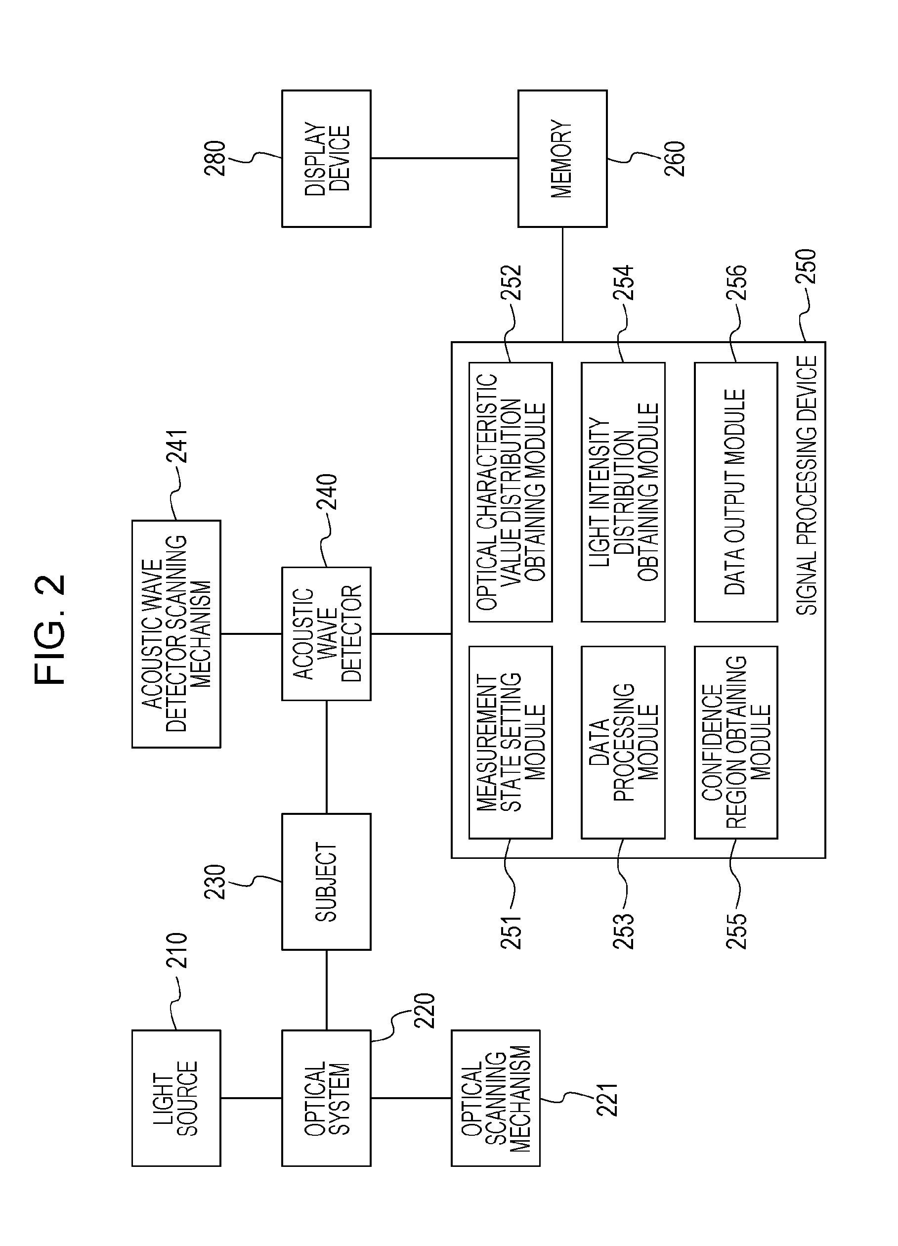
[0043]FIG. 2 is a block diagram illustrating a configuration of a subject information obtaining device according to the present embodiment, and is configured of a light source 210, an optical system 220, an optical scanning mechanism 221, a subject 230, an acoustic wave detector 240, an acoustic wave detector scanning mechanism 241, a signal processing device 250, memory 260, and a display device 280. The signal processing device 250 according to the present embodiment includes a measurement state setting module 251 serving as a measurement state setting unit, an optical characteristic value distribution obtaining module 252 serving as an optical characteristic value distribution obtaining unit, a data processing module 253 serving as a data processing unit, a light intensity distribution obtaining module 254 serving as a light intensity distribution obtaining unit, a confidence region obtaining module 255 serving as a confidence region obtaining unit, and a data output module 256.

[...

second embodiment

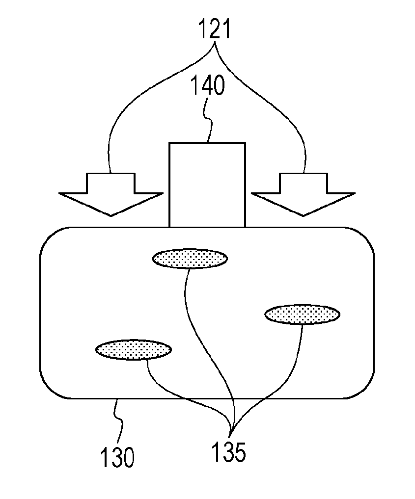
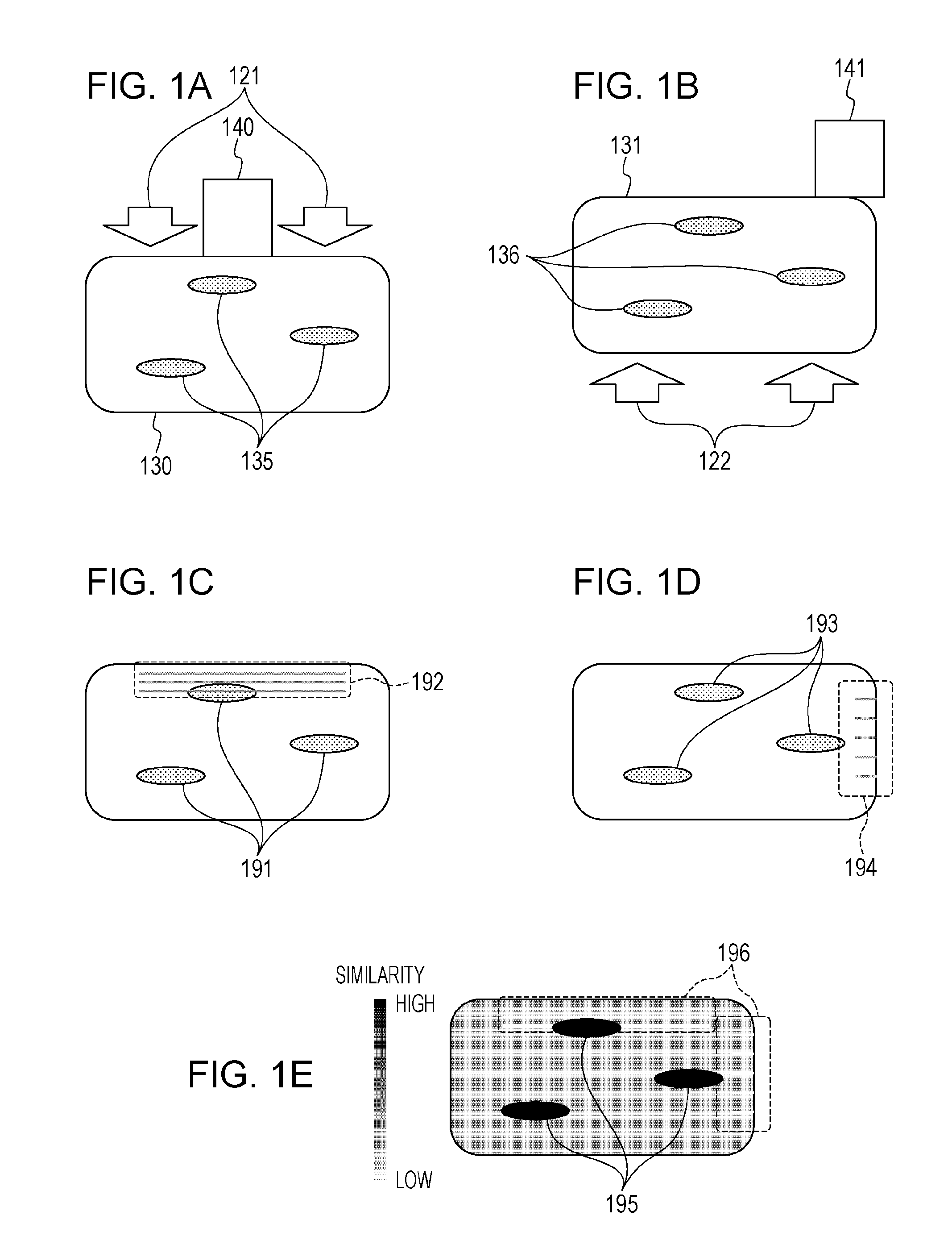
[0121]The present embodiment differs from other embodiments in that a light intensity distribution within a subject in each measurement state is displayed in addition to an optical characteristic value distribution obtained in each measurement state. Here, the light intensity distribution includes data to be displayed on the display unit, obtained by performing luminance value conversion on the light intensity distribution.

[0122]Incidentally, initial sound pressure PO of photoacoustic waves depends on light intensity Φ as represented with a relation in Expression (5).

P0=Γ·Φ·μa  (5)

[0123]Here, Γ represents a Grueneisen constant, and μa represents an optical absorption coefficient. As represented with Expression (5), when light intensity irradiated on an optical absorber has a great value, initial sound pressure of photoacoustic waves to be generated also increases. Specifically, an SN ratio of a detection signal corresponding to a region where much light intensity is irradiated incre...

third embodiment

[0139]The present embodiment differs from other embodiments in that of a light intensity distribution, a confidence region which is a region where light is sufficiently irradiated is obtained. The confidence region mentioned here includes data to be displayed on the display unit obtained by performing luminance value conversion on the confidence region.

[0140]With the photoacoustic imaging, it is desirable that of the light intensity distribution obtained in the second embodiment, a region where light is sufficiently irradiated is displayed in an enhanced manner. This is because a detection signal corresponding to a region where light is sufficiently irradiated is high in an SN ratio and high in reliability.

[0141]Hereinafter, a subject information obtaining method using a confidence region will be described with reference to the flowchart illustrated in FIG. 13. Note that the same processing as with the flowchart illustrated in FIG. 3 will be denoted with the same processing number, ...


PUM


Abstract

A subject information obtaining device according to the present disclosure includes: a first optical characteristic value distribution obtaining unit configured to obtain a first optical characteristic value distribution based on a first detection signal obtained by detecting first photoacoustic waves generated by irradiating light in a first measurement state on a subject; a second optical characteristic value distribution obtaining unit configured to obtain a second optical characteristic value distribution based on a second detection signal obtained by detecting second photoacoustic waves generated by irradiating light in a second measurement state different from the first measurement state on the subject; and a data processing unit configured to obtain a similarity distribution based on the first optical characteristic value distribution and the second optical characteristic value distribution.

Description

BACKGROUND OF THE INVENTION[0001]1. Field of the Invention[0002]One disclosed aspect of the embodiments relates to a subject information obtaining device, a subject information obtaining method, and a non-transitory computer-readable storage medium, which obtain subject information by detecting photoacoustic waves generated by light being irradiated.[0003]2. Description of the Related Art[0004]With the medical field, in recent years, photoacoustic imaging (PAI) whereby living body function information is obtained using light and ultrasonic waves has been proposed as one of devices capable of imaging the interior of a living body noninvasively, and its development has advanced.[0005]The photoacoustic imaging mentioned here is technology to irradiate pulsed light generated from a light source upon a subject, and image internal tissue serving as a generation source of photoacoustic waves, using photoacoustic advantages that photoacoustic waves (typically, ultrasonic waves) are generate...

Claims


Application Information

Patent Timeline
IPC IPC(8): A61B5/00
CPCA61B5/14551A61B5/0095
Inventor OISHI, TAKUJI
Owner CANON KK
Why Eureka
Try Eureka