System and method for recovery of waste heat from dual heat sources

Active Publication Date: 2013-09-26
NUOVO PIGNONE TECH SRL
View PDF8 Cites 11 Cited by
  • Summary
  • Abstract
  • Description
  • Claims
  • Application Information

AI Technical Summary

Benefits of technology

[0008]In accordance with one exemplary embodiment disclosed herein, a waste heat recovery system including a combustion engine and a heat recovery cycle system. The combustion engine including one heat source having an engine exhaust unit and at least one additional heat source selected from the group comprising a lower temperature intercooler, a higher temperature intercooler, a low pressure compressor exhaust unit, or combinations thereof. The one heat source comprising a higher temperature heat source than the at least one additional heat source. The heat recovery cycle system including a heater, a cooling unit, at least two expanders, a first heat exchange unit and a second heat exchange unit. The heat recovery cycle system is coupled to the engine exhaust unit and the at least one additional heat source and configured to circulate a working fluid. The first heat exchange unit is coupled to the heater and the at least one additional heat source, wherein at least a portion of the working fluid is circulatable in heat exchange relationship through the first heat exchange unit for heating of the working fluid in the heat recovery cycle system. At least a portion of the working fluid is circulatable in heat exchange relationship through the second heat exchange unit for heating of the working fluid in the heat recovery cycle system. The heat recovery cycle system is configured to remove heat from the engine exhaust unit and the at least one additional heat source.
[0009]In accordance with one exemplary embodiment disclosed here

Problems solved by technology

Although bottoming cycles can be used to recover additional electrical or shaft power from the hot exhaust gases given off by the engine, they are generally not configured to make efficient use of the available lower-temperature heat sources.
When waste heat is low grade, such as waste heat having a temperature below 300 degrees Celsius, for example, conventional heat recovery systems do not operate with sufficient efficiency to make recovery of energy cost-effective.
The net result is that vast quantities of waste heat are simply dumped into the atmosphere, ground, or water.
An undesirable result of th

Method used


Image

  • System and method for recovery of waste heat from dual heat sources
  • System and method for recovery of waste heat from dual heat sources

Examples


Embodiment Construction

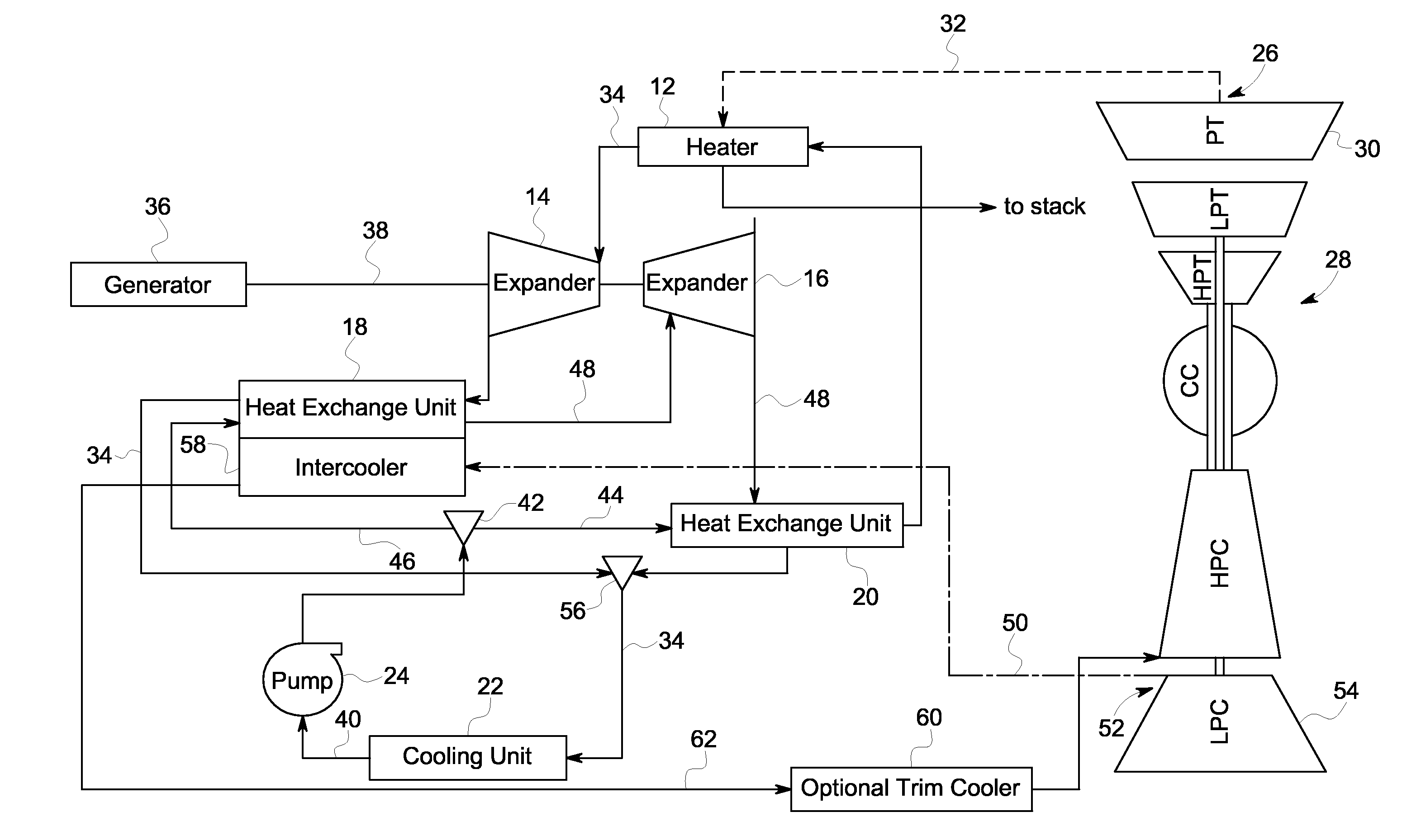
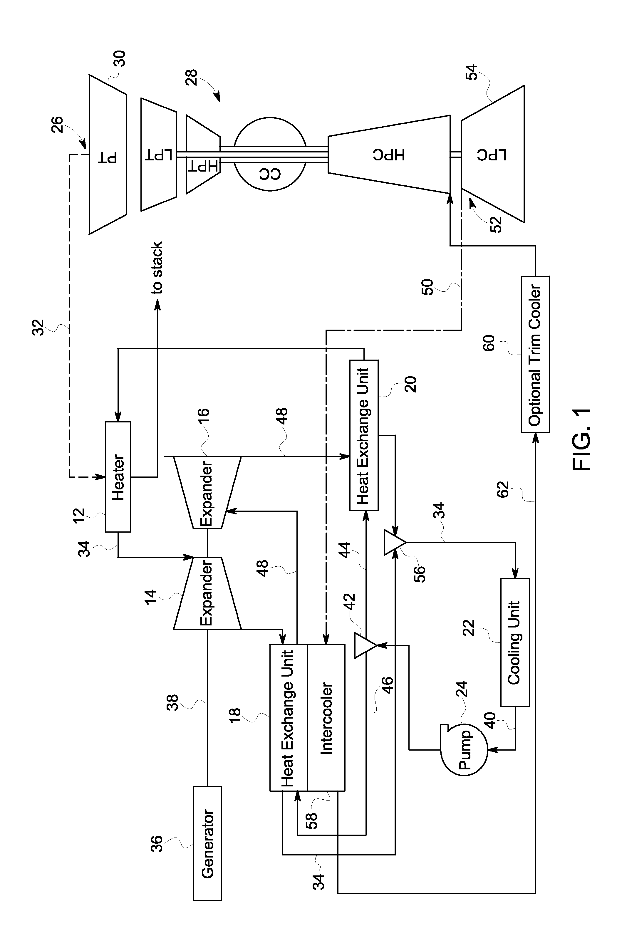
[0013]In accordance with the embodiment discussed herein, a heat recovery cycle system for recovering waste heat from dual sources is disclosed. The exemplary heat recovery cycle system includes a heater configured to circulate a working fluid in heat exchange relationship with a hot fluid so as to vaporize the working fluid. The heat recovery cycle system includes a first heat exchange unit configured to circulate a first vaporized stream of the working fluid from the heater in heat exchange relationship with a first portion of a cooled stream of the working fluid so as to heat the first portion of the cooled stream of the working fluid. The heat recovery cycle system further includes a second heat exchange unit configured to circulate a second vaporized stream of the working fluid in heat exchange relationship with a second portion of a cooled stream of the working fluid so as to heat the second portion of the cooled stream of the working fluid before being re-fed to the heater. I...


PUM


Abstract

A waste heat recovery system includes a heat recovery cycle system coupled to at least two separate heat sources having different temperatures. The heat recovery cycle system is coupled to a first heat source and at least one second heat source. The heat recovery cycle system is configured to circulate a working fluid. The at least one second heat source includes a lower temperature heat source than the first heat source. The working fluid is circulatable in heat exchange relationship through a first heat exchange unit, a second heat exchange unit for heating the working fluid in the heat recovery cycle system. The first heat exchange unit is coupled to the at least one second heat source to heat at least a portion of a cooled stream of working fluid to a substantially higher temperature.

Description

BACKGROUND[0001]The embodiments disclosed herein relate generally to the field of power generation and, more particularly, to a system and method for recovering waste heat from a plurality of heat sources having different temperatures for generation of electricity.[0002]Enormous amounts of waste heat are generated by a wide variety of industrial and commercial processes and operations. Example sources of waste heat include exhaust streams and heat from space heating assemblies, steam boilers, engines, and cooling systems. Many fuel-burning engines, besides producing an exhaust stream at high temperature, also give off heat at a lower temperature in lubricating oil, cooling fluid, or compressor intercooler air. Although bottoming cycles can be used to recover additional electrical or shaft power from the hot exhaust gases given off by the engine, they are generally not configured to make efficient use of the available lower-temperature heat sources.[0003]When waste heat is low grade,...

Claims


Application Information

Patent Timeline
IPC IPC(8): F01K27/00F28F27/02F28D15/00
CPCF01K7/42F01K23/10F22B35/086F22B1/1815F01K25/103Y02P80/15Y02T10/12
Inventor LEHAR, MATTHEW ALEXANDERMICHELASSI, VITTORIO
Owner NUOVO PIGNONE TECH SRL
Why Eureka
Try Eureka