Wet brake device

a technology of wet brakes and side brakes, which is applied in the direction of brake cooling, braking systems, fluid actuated brakes, etc., can solve the problems that the side brake disk and the non-rotating side brake disk cannot be sufficiently cool, and achieve the effect of reducing the rotation speed of the motor shaft and efficient cooling the whole periphery

Active Publication Date: 2013-09-26
NIHON KENKI CO LTD
View PDF3 Cites 23 Cited by
  • Summary
  • Abstract
  • Description
  • Claims
  • Application Information

AI Technical Summary

Benefits of technology

[0023]With this arrangement, since the rotational shaft extends in the vertical direction in the brake case, the lubricant oil having flowed into the brake case from the lubricant oil inlet port flows in the horizontal direction on the frictional engaging surface between the rotating side brake disk and the non-rotating side brake disk and can efficiently cool the whole periphery of the frictional engaging surface.
[0024](6) The present invention is configured such that the rotational shaft is a motor shaft of an electric motor provided on the lower side of the brake case; and the electric motor is provided on the upper side of a reduction device which reduces the rotation speed of the motor shaft.

Problems solved by technology

However, the above-described conventional art has a problem that a frictional engaging surface between the rotating side brake disk and the non-rotating side brake disk cannot sufficiently cooled at the time of rapid braking for braking the rotational shaft rotating at a high load and a high speed, an emergency stop and the like, for example.

Method used


Image

  • Wet brake device
  • Wet brake device
  • Wet brake device

Examples


Embodiment Construction

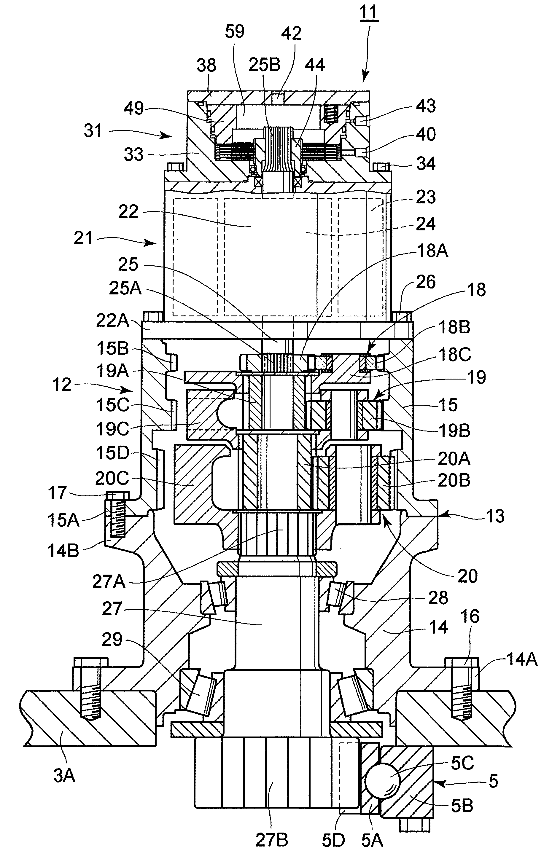
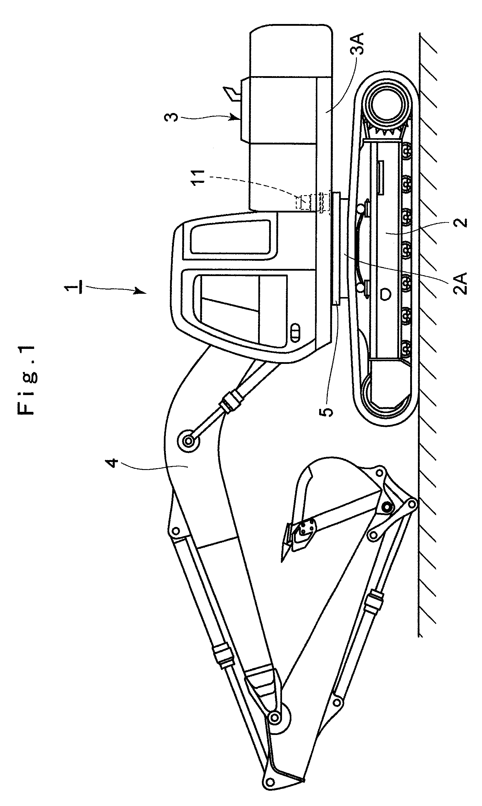
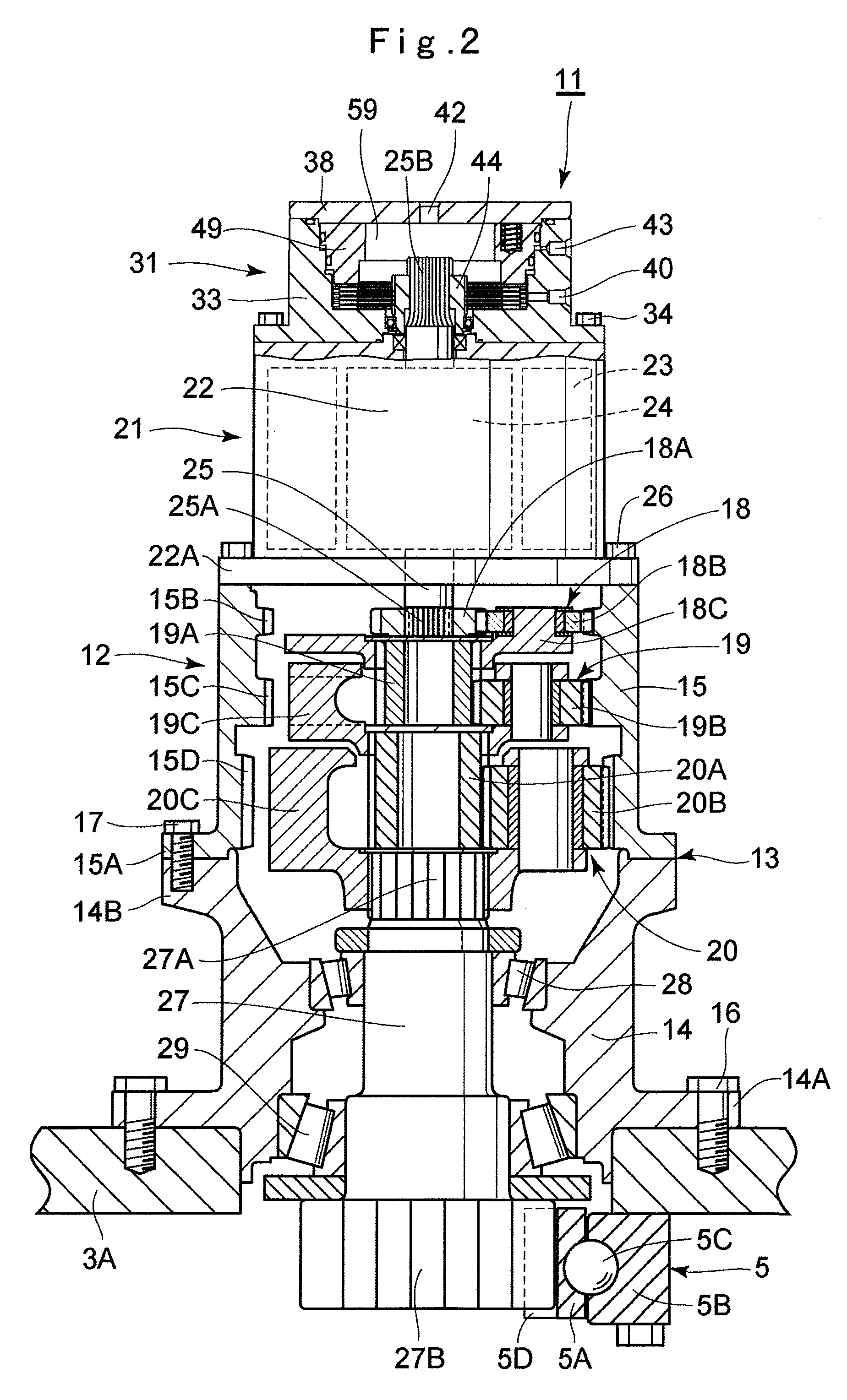
[0038]Hereafter, an embodiment of a wet brake device according to the present invention will be in detail explained with reference to the accompanying drawings FIG. 1 to FIG. 10, by taking a case in which the wet brake device is applied to a revolving apparatus equipped in a hydraulic excavator as an example.

[0039]In Figures, designated at 1 is a hydraulic excavator which is a typical example of a revolving type construction machine, and the hydraulic excavator 1 is formed of an automotive crawler-type lower traveling structure 2 and an upper revolving structure 3 rotatably mounted on the lower traveling structure 2. On the front portion side of the upper revolving structure 3, a working mechanism 4 is liftably provided. A swing circle 5, which will be described later, is provided between the lower traveling structure 2 and the upper revolving structure 3, and the upper revolving structure 3 is rotatably supported on the lower traveling structure 2 through the swing circle 5.

[0040]T...


PUM


Abstract

A plurality of rotating side brake disks and a plurality of non-rotating side brake disks are arranged outside in the radial direction from a motor shaft in a brake case while alternately overlapping with each other. A frictional material is provided on the non-rotating side brake disk, and an oil groove is provided in a frictional engaging surface of this frictional material. It is configured such that, when a braking force is applied by a brake piston to the motor shaft, lubricant oil flowing into the brake case from a lubricant oil inlet port flows from the outer diameter side to the inner diameter side between the rotating side brake disk and the non-rotating side brake disk only through the oil groove. As a result, the lubricant oil having flowed into the brake case efficiently cools the frictional engaging surface.

Description

TECHNICAL FIELD[0001]The present invention relates to a wet brake device used for a revolving apparatus equipped in a revolving type construction machine such as a hydraulic excavator, hydraulic crane and the like, for example, and applying a braking force to a rotational shaft.BACKGROUND ART[0002]In general, a hydraulic excavator as a typical example of a revolving type construction machine is largely constituted by an automotive lower traveling structure, an upper revolving structure that is rotatably mounted on the lower traveling structure through a swing circle, and a working mechanism provided on the front portion side of the upper revolving structure. A revolving apparatus is provided between the lower traveling structure and the upper revolving structure, and the upper revolving structure is configured to be revolved on the lower traveling structure by operating this revolving apparatus.[0003]The revolving apparatus includes a reduction device which is mounted on the upper r...

Claims


Application Information

Patent Timeline
Patent Type & Authority Applications(United States)
IPC IPC(8): F16D65/833
CPCB60T1/062B60T5/00E02F9/128F16D55/36F16D65/853F16D2055/0058B66C23/86F16D2069/004F16D2121/06H02K7/102H02K7/116H02K9/19F16D65/833F16D2065/783F16D55/40F16D59/02
Inventor OKUNO, NAOYUKIKOMARU, YUTAKANIIDOME, TAKASHI
Owner NIHON KENKI CO LTD
Why Eureka
Try Eureka