
Bitumen froth storage and separation using an improved froth tank

Inactive Publication Date: 2013-09-26
SYNCRUDE CANADA LTD
View PDF3 Cites 5 Cited by
  • Summary
  • Abstract
  • Description
  • Claims
  • Application Information

AI Technical Summary

Benefits of technology

The patent is about a process for separating bitumen froth from water. The process has a specific time range for the bitumen to stay in the system, between two to twenty-four hours. The ratio of the two liquids, bitumen and water, is controlled to allow for better separation, with a preferred ratio of about 7.5%. The temperature of the bitumen froth is set between 70-90°C, which allows the bitumen to move upwards and the water to move downwards, leading to better separation.

Problems solved by technology

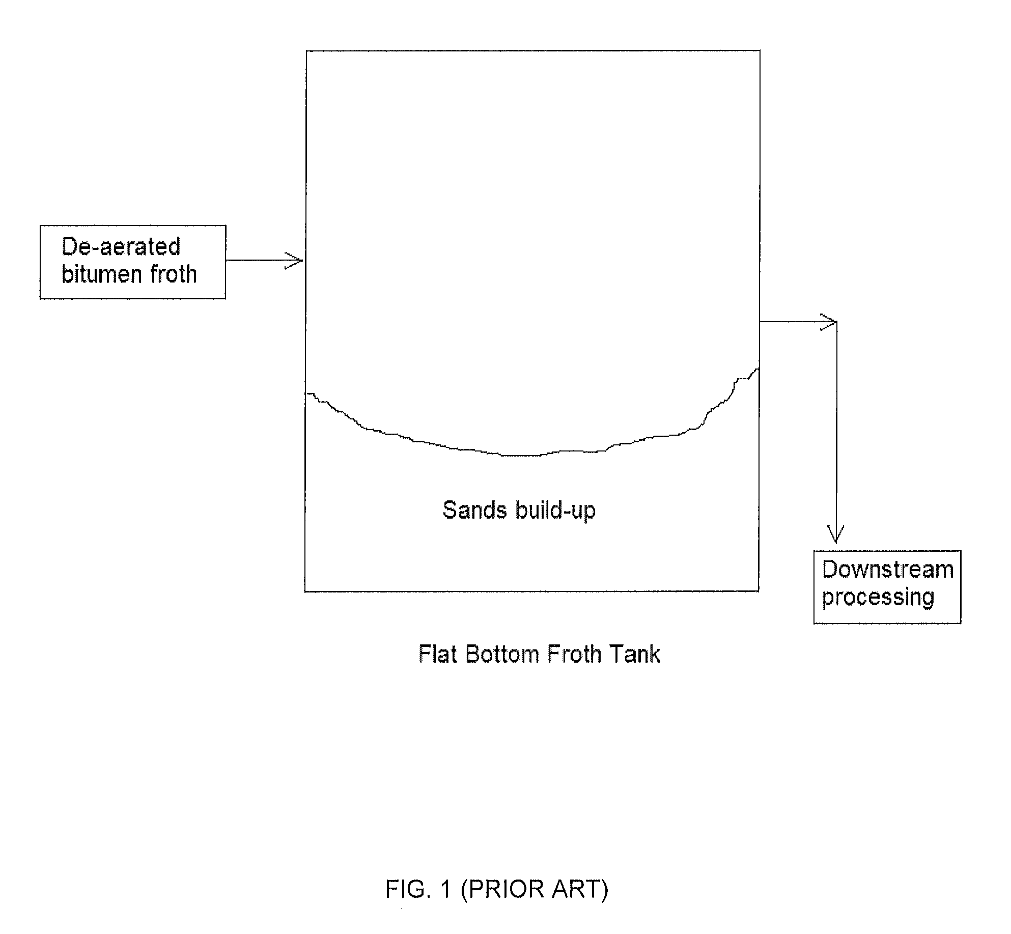
Removal of the settled solids from the tank using a pump is often unsuccessful due to the loss of the solids slurry / froth interface.
This loss is attributed to the uneven settling of solids on the bottom of the tank coupled with uneven removal resulting from coning of the solids.
The solids build-up reduces both the capacity and ability of the tank to act as a surge vessel.
The uneven deposition of solids can result in periodic sloughing of solids into the froth treatment process during times of low tank levels or large rate changes, causing major upsets in downstream equipment including, for example, overload of centrifuges and filters.
In addition, conventional froth storage tanks tend to have limited mixing capability.

Method used


Image

  • Bitumen froth storage and separation using an improved froth tank
  • Bitumen froth storage and separation using an improved froth tank
  • Bitumen froth storage and separation using an improved froth tank

Examples


example 1

Testing of Cone-Bottomed, Raked Froth Tank

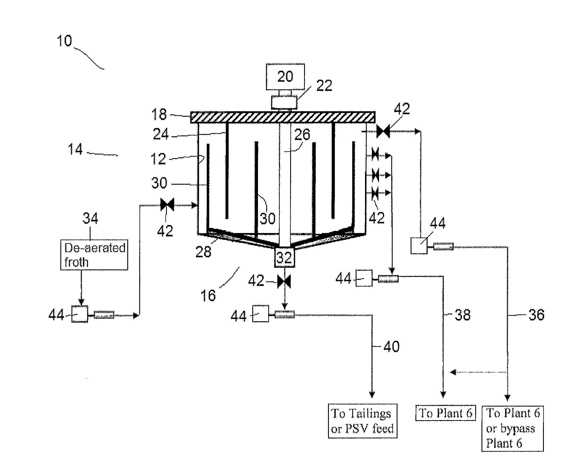
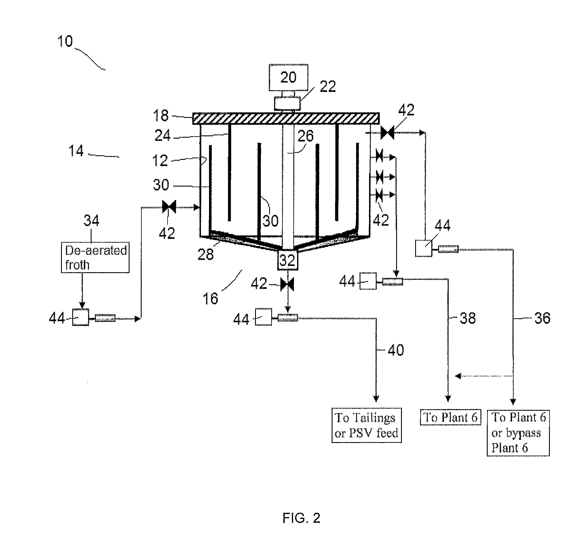
[0044]Pilot tests were conducted to assess the ability of a cone-bottomed, raked froth tank to function as a froth cleaner and storage tank; the effects of bulk froth residence time, underflow split ratios, and feed compositions on solids / water and bitumen separation in the froth tank; and the effect of stationary and movable pickets along with the rake arms on the separation of solids / water and bitumen.

[0045]The test conditions are summarized in Table 1:

TABLE 1Test ConditionsFixedFroth temperature: 80° C.variablesRake turned-on at 1.24 rpm with moving and static picketsElevation of feed injection: 1 m above the knuckleElevation of middlings withdrawal: 1.5 m above the knuckleOperating level of froth in the tank: 2 m above the knuckleDe-aerated froth obtained from Aurora froth tankIndependentBulk froth residence time: 1, 2 and 4 hours by changingvariablesfeed flow rates from 3, 1.5 to 0.75 L / sUnderflow split ratios: 3.75%, 7.5%, 15% and 50% ...

example 2

Specifications for an Exemplary Cone-Bottomed, Raked Froth Tank

[0051]A suitable froth tank may be approximately forty meters in diameter, about eighteen meters in height, about 23,000 m3 in volume, and have a cone slope of 1:6 in order to process about 1200 to 3500 m3 per hour of feed, and to ensure the discharge of solids as tailings. The residence time may range between about 6 to 18 hours. The froth tank has an available volume for feed of about 20,000 m3 and operates at a level between about 15-90%. The nominal capacity is about 125 kBBL.


PUM

PropertyMeasurementUnit
Temperatureaaaaaaaaaa
Fractionaaaaaaaaaa

Abstract

The invention is directed to a process for separating bitumen froth into an upper bitumen-rich, reduced-solids layer, and a lower concentrated solids layer using a cone-bottomed, raked froth tank. The process involves introducing bitumen froth into the froth tank; rotating at least one movable picket through the bitumen froth; recovering the upper bitumen-rich, reduced-solids layer; and withdrawing the lower concentrated solids layer from the tank.

Description

FIELD OF THE INVENTION[0001]The present invention relates generally to the field of oil sands processing, particularly to a process for storing and separating bitumen froth using an improved froth tank.BACKGROUND OF THE INVENTION[0002]Oil sand deposits such as those found in the Athabasca Region of Alberta, Canada, generally comprise water-wet sand grains held together by a matrix of viscous heavy oil or bitumen. Bitumen is a complex and viscous mixture of large or heavy hydrocarbon molecules which contain a significant amount of sulfur, nitrogen and oxygen. Oil sands processing involves mining the oil sand, bitumen water extraction and bitumen froth treatment to produce diluted bitumen which is further processed to produce synthetic crude oil and other valuable commodities.[0003]Extraction is typically conducted by mixing the oil sand with steam, hot water and caustic. After extraction, the froth is initially stored in a large capacity froth storage tank until a sufficient volume i...

Claims


Application Information

Patent Timeline
IPC IPC(8): C10G1/04C10C3/08
CPCB01D21/286C10G1/045B01D21/34B01D2221/04B01D21/06B03D2203/006B03D1/1493C10C3/08B01D21/2427
Inventor YUAN, SIMONLORENTZ, JIMVANDENBERGHE, JESSICA
Owner SYNCRUDE CANADA LTD
Learn More