Magnetic Field Sensor Integrated Circuit with Integral Ferromagnetic Material

a magnetic field sensor and integrated circuit technology, applied in the field of magnetic field sensors, can solve the problems of relatively high cost of hard magnetic materials used to form magnets and represent a significant part of the overall cost of sensors

Active Publication Date: 2013-09-26
ALLEGRO MICROSYSTEMS INC
View PDF9 Cites 42 Cited by
  • Summary
  • Abstract
  • Description
  • Claims
  • Application Information

AI Technical Summary

Benefits of technology

[0013]In one aspect of the invention, a magnetic field sensor includes a lead frame, a semiconductor die supporting a magnetic field sensing element and attached to the lead frame, a non-conductive mold material enclosing the die and at least a portion of the lead frame, a ferromagnetic mold material secured to a portion of the non-conductive mold material, and a securing mechanism by whi

Problems solved by technology

While the use of a back bias magnet is advantageous in certain applications, the hard magnetic material used to form the magnet is relatively expensive and represents a significant part of the overall cost of th

Method used


Image

  • Magnetic Field Sensor Integrated Circuit with Integral Ferromagnetic Material
  • Magnetic Field Sensor Integrated Circuit with Integral Ferromagnetic Material
  • Magnetic Field Sensor Integrated Circuit with Integral Ferromagnetic Material

Examples


embodiment 340

[0123]Another magnetic field sensor embodiment 340, that may be formed by dicing the semiconductor wafer 250 of FIG. 9 into individual die, is shown in FIG. 13 to include a semiconductor die 344 having a first surface 344a over which the layer 346 of ferromagnetic material is formed and a second opposing surface 344b. A magnetic field sensing element 348 (shown as a Hall sensor in the substrate or epi layer) and associated circuitry (not shown) are disposed in the first surface 344a of the die. TSVs 350 are formed through the die 344 to couple the magnetic field sensing element 348 to solder balls 352, as shown, for further coupling to a lead frame that may be the same as or similar to any of the above-described lead frames. An optional layer 354 may be provided between the die surface 344a and the layer 346 in order to protect the die from particles in the layer 346. In such embodiments, the layer 354 may comprise, but is not limited to, a polyimide or BCB layer deposited at the wa...

embodiment 400

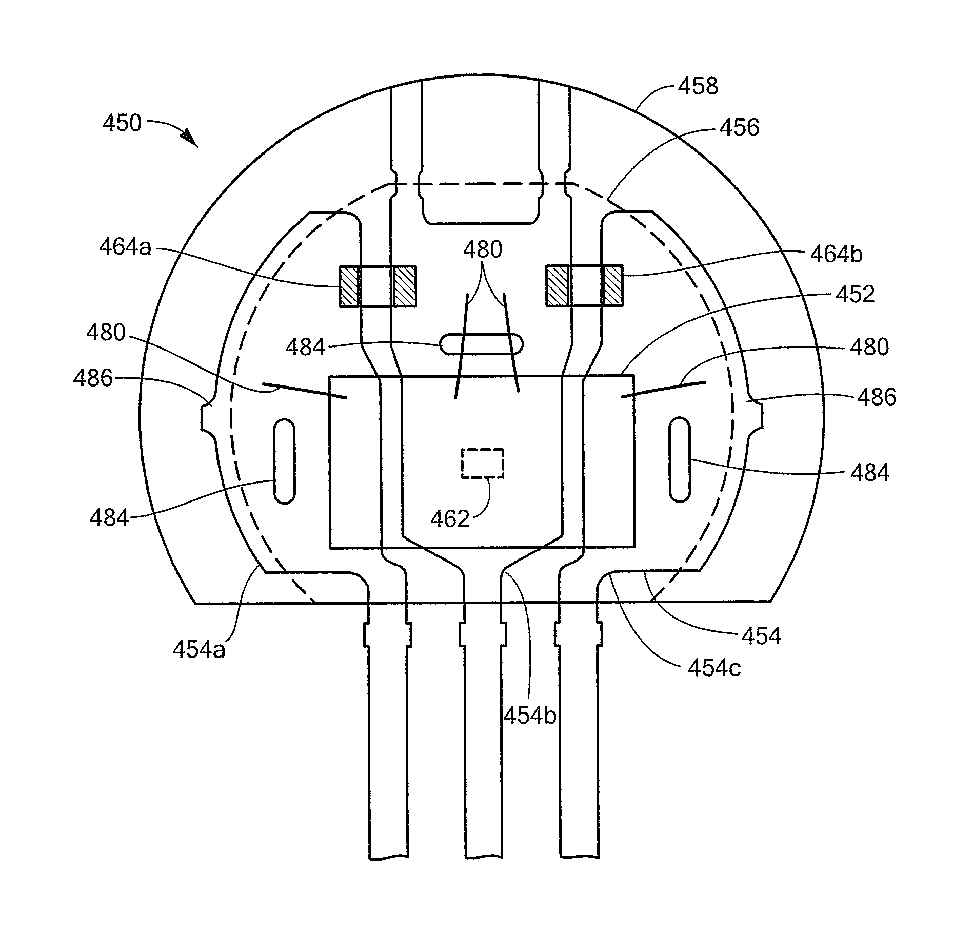
[0128]Another magnetic field sensor embodiment 400 is shown in FIG. 15 to include a semiconductor die 402 having a first, active surface 402a in which a magnetic field sensing element 404 is formed and a second, opposing surface 402b. A lead frame 406 having leads 406a-406c is provided with a die attach area 406d to which the surface 402b of the die 402 is attached, such as with the use of adhesives, such as epoxy or an adhesive tape.

[0129]A bias magnet 410 is provided with a non-contiguous central region 410a. As in the above-described embodiments, the bias magnet 410 may take the form of a ring-shaped structure in which case the non-contiguous central region is an aperture or alternatively may form only a partial or alternative ring-shaped structure, such as a D-shaped structure, a C-shaped structure, or a U-shaped structure.

[0130]The magnet 410 includes one or more channels 410b extending laterally from the central region 410a. The die / lead frame / magnet subassembly is overmolded ...


PUM


Abstract

A magnetic field sensor includes a lead frame, a semiconductor die supporting a magnetic field sensing element, a non-conductive mold material enclosing the die and a portion of the lead frame, a ferromagnetic mold material secured to the non-conductive mold material and a securing mechanism to securely engage the mold materials. The ferromagnetic mold material may comprise a soft ferromagnetic material to form a concentrator or a hard ferromagnetic material to form a bias magnet. The ferromagnetic mold material may be tapered and includes a non-contiguous central region, as may be an aperture or may contain the non-conductive mold material or an overmold material. Further embodiments include die up, lead on chip, and flip-chip arrangements, wafer level techniques to form the concentrator or bias magnet, integrated components, such as capacitors, on the lead frame, and a bias magnet with one or more channels to facilitate overmolding.

Description

CROSS REFERENCE TO RELATED APPLICATIONS[0001]Not Applicable.STATEMENT REGARDING FEDERALLY SPONSORED RESEARCH[0002]Not Applicable.FIELD OF THE INVENTION[0003]This invention relates generally to magnetic field sensors and, more particularly, to integrated circuit magnetic field sensors having an integral ferromagnetic material.BACKGROUND OF THE INVENTION[0004]Magnetic field sensors including a magnetic field sensing element, or transducer, such as a Hall Effect element or a magnetoresistive element, are used in a variety of applications to detect aspects of movement of a ferromagnetic article, or target, such as proximity, speed, and direction. Illustrative applications include, but are not limited to, a magnetic switch or “proximity detector” that senses the proximity of a ferromagnetic article, a proximity detector that senses passing ferromagnetic articles (for example, magnetic domains of a ring magnet or gear teeth), a magnetic field sensor that senses a magnetic field density of...

Claims


Application Information

Patent Timeline
IPC IPC(8): G01R33/02
CPCG01R33/0047G01R33/0011H01L2224/48247H01L2924/19105H01L2224/73215H01L2224/4826G01B7/30G01D5/145G01R33/072G01R15/202
Inventor VIG, RAVITAYLOR, WILLIAM P.FRIEDRICH, ANDREAS P.DAVID, PAULLO, MARIE-ADELAIDEBURDETTE, ERICSHOEMAKER, ERICDOOGUE, MICHAEL C.
Owner ALLEGRO MICROSYSTEMS INC
Why Eureka
Try Eureka