Apparatus for improving stencil/screen print quality

a stencil and screen printing technology, applied in the field of stencils and screen printing, can solve the problems of reducing the screen life, poor patterned layer, shortening the screen life, etc., and slowed down the screen and stencil printing process. , to achieve the effect of promoting the spread of printable materials, minimizing the migration of printable materials, and low surface tension

Inactive Publication Date: 2009-01-13
MICRON TECH INC
View PDF26 Cites 0 Cited by
  • Summary
  • Abstract
  • Description
  • Claims
  • Application Information

AI Technical Summary

Benefits of technology

[0007]For example, the pattern may include a number of apertures. The side walls of these apertures are side surfaces of the pattern. During the printable material application process, the stencil or screen is aligned over the substrate to which the printable material is to be applied. The bottom surface of the screen or stencil is coated with a material such as polytetrafloroethylene or another polymeric material to retard running of the printable material onto the bottom surface (i.e., between the stencil or screen and the substrate). The top surface and side surfaces of the pattern are alternatively coated with a material such as tungsten to promote spreading of the printable material from the top and side surfaces to the parts of the object surface exposed underneath.
[0008]The material coating the bottom surface of the pattern, which is desirably a polymeric material, in accordance with an embodiment of the invention, has three advantageous aspects. First, it acts as a low surface tension layer to minimize printable material migration in order to provide better print definition. Second, it acts as a gasket layer to constrain the flow of the printable material. Third, it acts as a buffer layer to minimize the stencil height inconsistency caused by defects, such as burr, on the bottom of the stencil and the top surface of the substrate onto which the printable material is applied.
[0009]A stencil or screen according to an embodiment of the invention therefore increases life of the stencil or screen. That is, consecutive prints can be made using a stencil or screen according to an embodiment of the invention without cleaning. This results in faster screen printing and reduces cost of the printing. Still other and further advantages, aspects and embodiments of the invention will become apparent by reference to the drawings and by reading the following detailed description.

Problems solved by technology

This results in a poorly patterned layer.
More significantly, migration underneath the bottom of the screen shortens screen life, which is defined as the number of consecutive uses, or prints, of the screen without cleaning of the screen.
Reduced screen life therefore slows down the screen and stencil printing process, and adds cost to the process.

Method used


Image

  • Apparatus for improving stencil/screen print quality
  • Apparatus for improving stencil/screen print quality
  • Apparatus for improving stencil/screen print quality

Examples


Embodiment Construction

[0016]In the following detailed description of the preferred embodiments, reference is made to the accompanying drawings which form a part hereof, and in which is shown by way of illustration specific preferred embodiments in which the inventions may be practiced. These embodiments are described in sufficient detail to enable those skilled in the art to practice the invention, and it is to be understood that other embodiments may be utilized and that logical, mechanical and electrical changes may be made without departing from the spirit and scope of the present invention. The following detailed description is, therefore, not to be taken in a limiting sense, and the scope of the present invention is defined only by the appended claims.

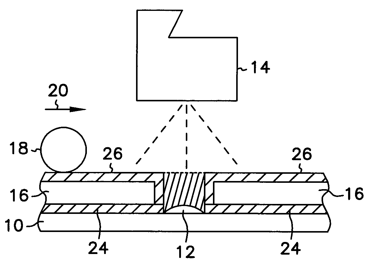
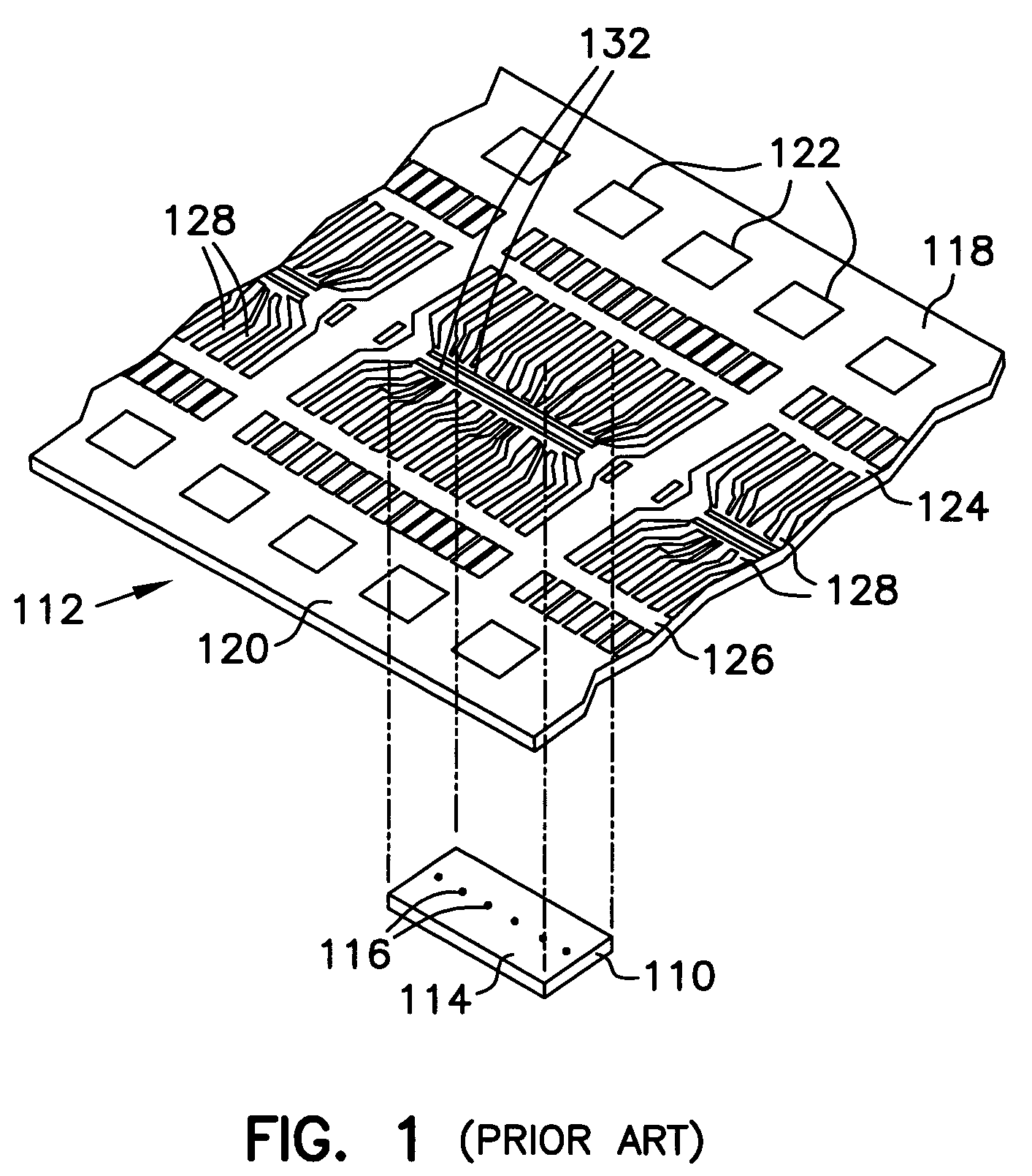
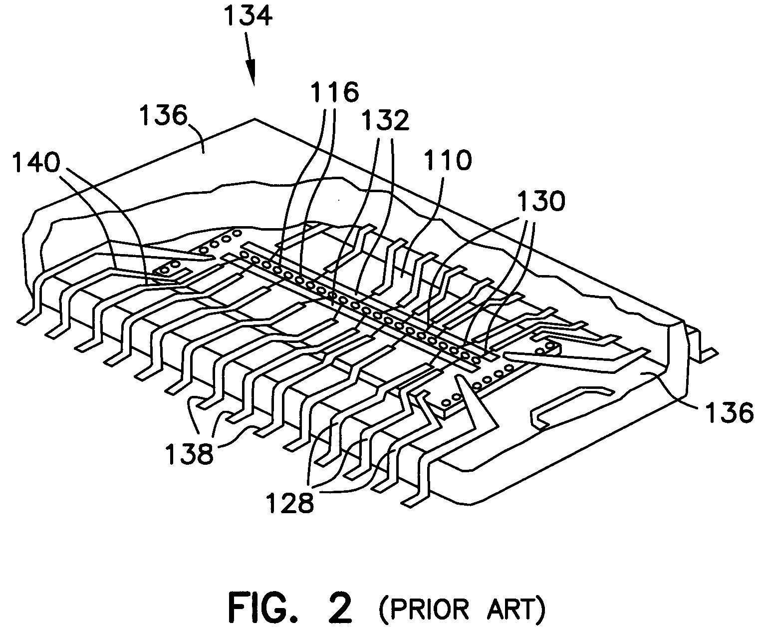
[0017]The invention as it is described in conjunction with FIGS. 1-4, 5(a) and 5(b) is described in relation to the application of an adhesive layer onto a semiconductor die so that the die may be attached to a lead frame. Those of ordinary skill withi...


PUM


Abstract

A method and apparatus for improved stencil / screen print quality is disclosed. The stencil or screen assists in application of a printable material onto a substrate, such as an adhesive to a semiconductor die of a semiconductor wafer during a lead-on-chip (LOC) packaging process. In one embodiment, the stencil includes a coating applied to at least one surface of a pattern of the stencil or screen to retard running of the printable material onto the surface. In another embodiment, the stencil or screen includes a second coating applied to at least one other surface of the pattern to promote spreading of the printable material onto the substrate.

Description

RELATED APPLICATION(S)[0001]This apication is a Divisional of U.S. application Ser. No. 09 / 513,934 filed on Feb. 28, 2000, now U.S. Pat. No. 6,641,669, which is a Divisional of U.S. application Ser. No. 08 / 935,745 filed Sep. 23, 1997, now U.S. Pat. No. 6,669,781. These applications are incorporated herein by reference.FIELD OF THE INVENTION[0002]This invention relates generally to stencil and screen prints, and particularly to improving the quality of such stencil and screen prints.BACKGROUND OF THE INVENTION[0003]Stencils and screens to apply patterns or printable material on substrates have been used in many contexts. For example, such a patterned adhesive layer, as described in Farnworth et al., U.S. Pat. No. 5,286,697, which is hereby incorporated by reference, may be used to attach a semiconductor die to a lead frame. Farnworth et al. describes the use of a patterned screen to deposit an adhesive layer on the die so that the die can be mounted to the lead frame. The screen is p...

Claims


Application Information

Patent Timeline
Patent Type & Authority Patents(United States)
IPC IPC(8): B05C11/00B41C1/14B41N1/24H05K3/12
CPCB41C1/14B41N1/242H05K3/1225Y10S438/945H01L2224/4826
Inventor JIANG, TONGBICOBBLEY, CHAD A.VANNORTWICK, JOHN
Owner MICRON TECH INC
Why Eureka
Try Eureka