Image processing device and image processing method

a technology of image processing and image processing, which is applied in the direction of signal generators with optical-mechanical scanning, color television with bandwidth reduction, etc., can solve the problems of reducing encoding efficiency and risk that such decreases in encoding efficiency accompanying the update of quantization matrix may become even more significant, and achieve the effect of moderated encoding efficiency

Active Publication Date: 2013-09-26
SONY CORP
View PDF5 Cites 78 Cited by
  • Summary
  • Abstract
  • Description
  • Claims
  • Application Information

AI Technical Summary

Benefits of technology

[0016]According to an image processing device and an image processing method in accordance with the present disclosure, it is possible to moderate the decrease in encoding efficiency accompanying the update of the quantization matrix.

Problems solved by technology

This means that the encoding efficiency will decrease because of increased overhead.
For HEVC, in which the quantization matrix size is further increased and in which several different quantization matrices may be defined for each picture, there is a risk that such decreases in the encoding efficiency accompanying the update of the quantization matrix may become even more significant.

Method used


Image

  • Image processing device and image processing method
  • Image processing device and image processing method
  • Image processing device and image processing method

Examples


first example

5-1. First Example

[0180]FIGS. 13 to 15 illustrate a first example of illustrative pseudo-code expressing the syntax of a QMPS according to the present embodiment. Line numbers are given on the left edge of the pseudo-code. Also, an underlined variable in the pseudo-code means that the parameter corresponding to that variable is specified inside the QMPS.

[0181]The function QuantizaionMatrixParameterSet( ) on line 1 in FIG. 13 is a function that expresses the syntax of a single QMPS. On line 2 and line 3, the QMPS ID (quantization_matrixparamter_id) and the generation mode present flag (pred_present_flag) are specified. The subsequent syntax from line 6 to line 56 loops for every size and type of quantization matrix. The syntax from line 7 to line 53 in the loop is inserted into the QMPS in the case where a generation mode is present (pred_present_flag=1).

[0182]The syntax from line 9 to line 16 in the case where a generation mode is present is the syntax for copy mode. From line 9 to ...

second example

5-2. Second Example

[0186]FIGS. 16 to 20 illustrate a second example of illustrative pseudo-code expressing the syntax of a QMPS according to the present embodiment.

[0187]The function QuantizaionMatrixParameterSet( ) on line 1 in FIG. 16 is a function that expresses the syntax of a single QMPS. On line 2, the QMPS ID (quantization_matrix_paramter_id) is specified. In addition, the generation mode present flag (pred_present_flag) is specified on line 6, except in the case where only the default quantization matrix is designated.

[0188]Furthermore, in the second example, four classes of quantization scales (Qscale0 to Qscale3) are specified from line 7 to line 10 in the function QuantizaionMatrixParameterSet( ) These quantization scales are parameters that may be adopted in order to quantize the value of each element in a quantization matrix and further decrease the rate. More specifically, four quantization scale setting areas A1 to A4 like those illustrated in FIG. 21 are defined in a...

example application

7. EXAMPLE APPLICATION

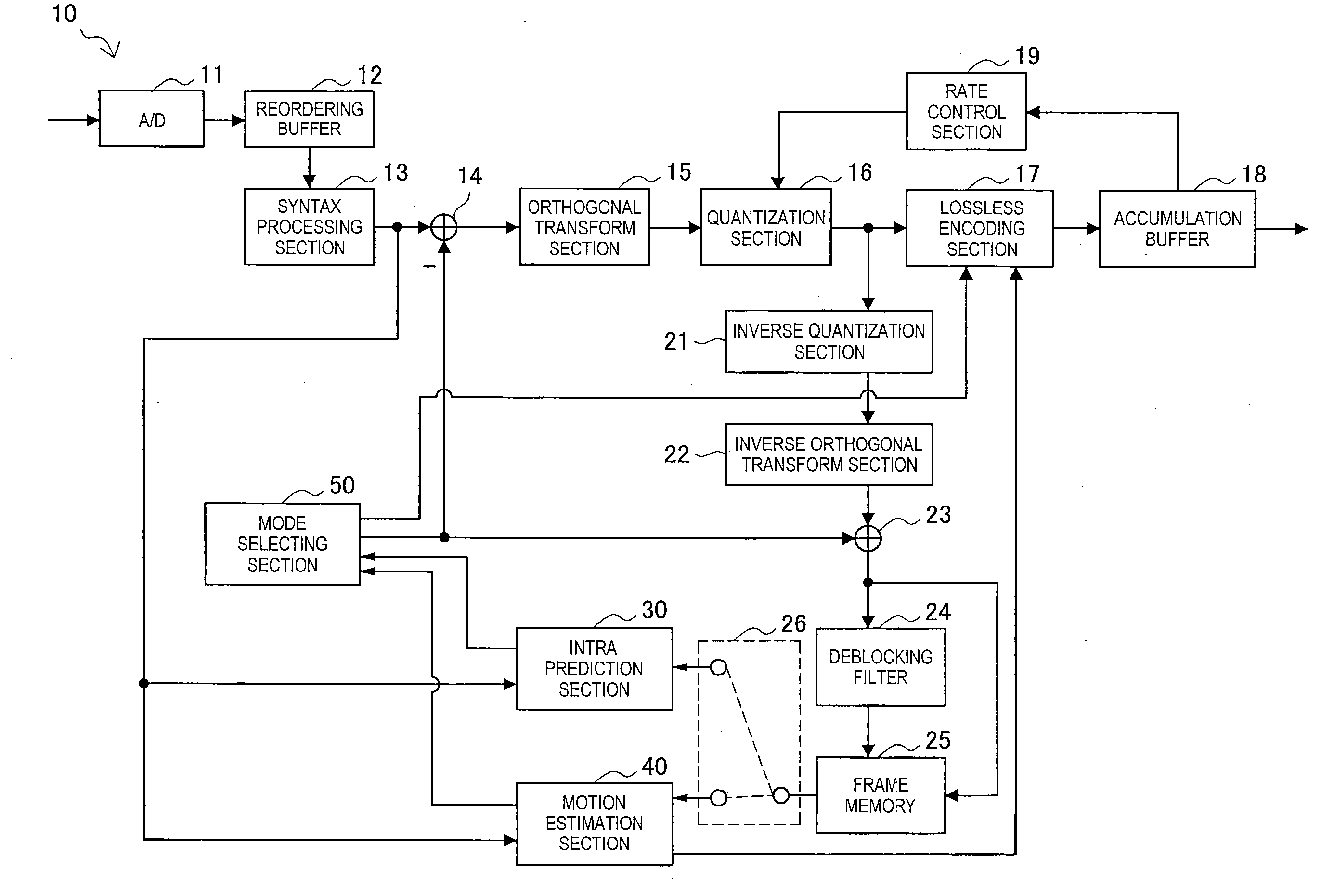
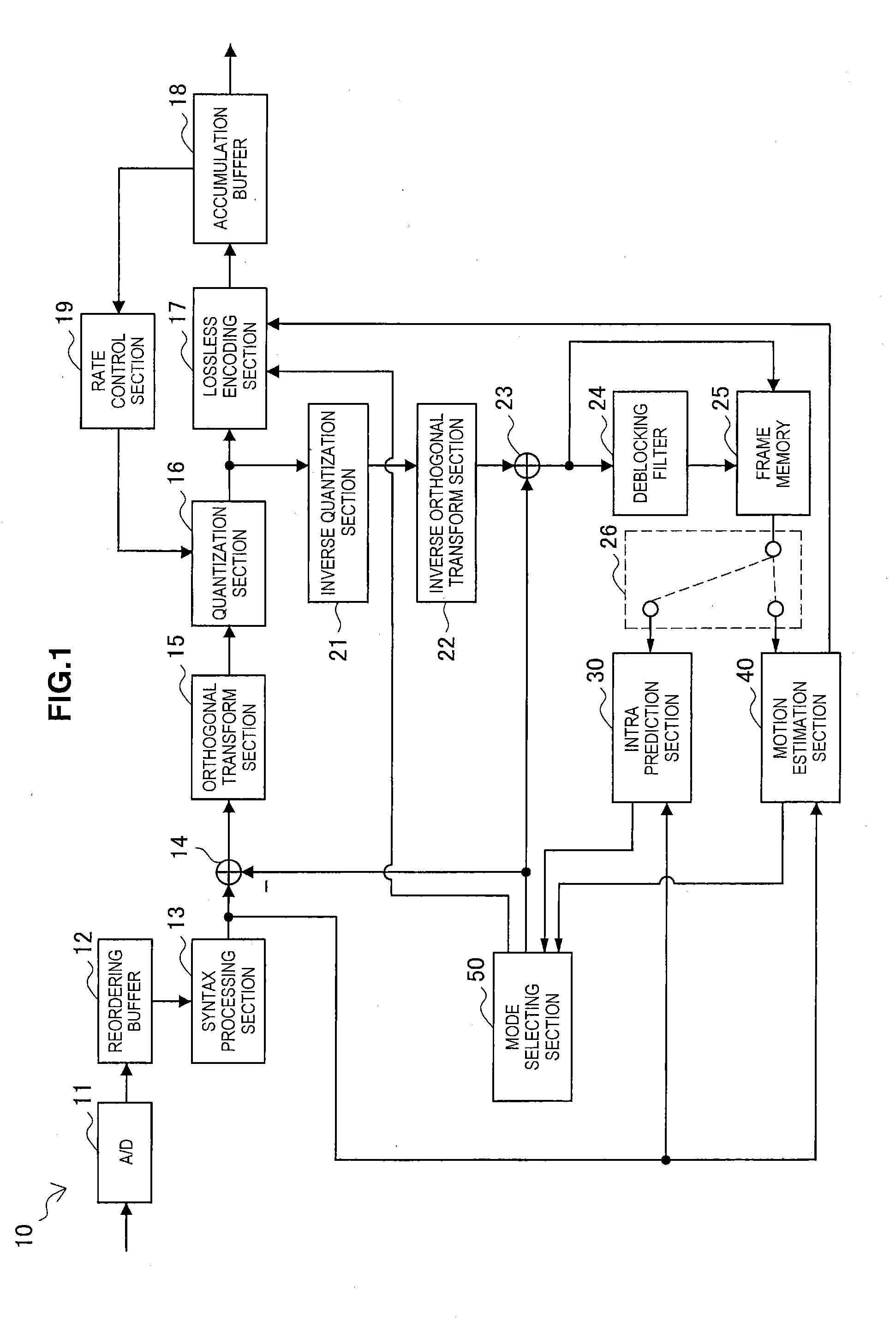
[0244]The image encoding device 10 and the image decoding device 60 according to the embodiment described above may be applied to various electronic appliances such as a transmitter and a receiver for satellite broadcasting, cable broadcasting such as cable TV, distribution on the Internet, distribution to client devices via cellular communication, and the like, a recording device that records images onto a medium such as an optical disc, a magnetic disk, or flash memory, and a playback device that plays back images from such storage media. Four example applications will be described below.


PUM


Abstract

An image processing device including an acquiring section configured to acquire quantization matrix parameters from an encoded stream in which the quantization matrix parameters defining a quantization matrix are set within a parameter set which is different from a sequence parameter set and a picture parameter set, a setting section configured to set, based on the quantization matrix parameters acquired by the acquiring section, a quantization matrix which is used when inversely quantizing data decoded from the encoded stream, and an inverse quantization section configured to inversely quantize the data decoded from the encoded stream using the quantization matrix set by the setting section.

Description

TECHNICAL FIELD[0001]The present disclosure relates to an image processing device and an image processing method.BACKGROUND ART[0002]In H.264 / AVC, one of the standard specifications for image encoding schemes, it is possible to use different quantization steps for each component of the orthogonal transform coefficients when quantizing image data in the High Profile or higher profile. A quantization step (or quantization scale) for each component of the orthogonal transform coefficients may be set on the basis of a quantization matrix (also called a scaling list) defined at the same size as the units of orthogonal transform, and a standard step value.[0003]FIG. 38 illustrates four classes of default quantization matrices which are predefined in H.264 / AVC. The matrix SL1 is the default 4×4 quantization matrix for intra prediction mode. The matrix SL2 is the default 4×4 quantization matrix for inter prediction mode. The matrix SL3 is the default 8×8 quantization matrix for intra predic...

Claims


Application Information

Patent Timeline
Patent Type & Authority Applications(United States)
IPC IPC(8): H04N7/26
CPCH04N19/44H04N19/10H04N19/31H04N19/50H04N19/176H04N19/157H04N19/46H04N19/103H04N19/124H04N19/126H04N19/70H04N19/174H04N19/463H04N19/159H04N19/51H04N19/61H04N19/86H04N19/105H04N19/186
Inventor TANAKA, JUNICHI
Owner SONY CORP
Why Eureka
Try Eureka