System and Method for Controlling Humidity in a Battery Module

a battery module and humidity control technology, applied in the field of battery environment management, can solve the problems of reducing the effectiveness of electrolytic materials in the battery cell, reducing the performance of battery cells, and reducing the effectiveness of battery cells, so as to achieve high voltage, increase the power density, and the effect of high voltag

Inactive Publication Date: 2013-09-26
A123 SYSTEMS LLC
View PDF1 Cites 24 Cited by
  • Summary
  • Abstract
  • Description
  • Claims
  • Application Information

AI Technical Summary

Benefits of technology

[0002]To meet increasing power density requirements and environmental constraints manufacturers have recently adopted new compounds for batteries. For example, some batteries contain may contain compounds such as LiCoO2 and LiMn2O4. These compounds may provide high voltage relative to weight. Further, such compounds may be formed into individual ba...

Problems solved by technology

However, when some battery compound formulations are exposed to humidity their performance may degrade.
In particular, water molecules in air surrounding a battery cell may react with the compound and reduce the effectiveness of electrolytic material in the battery ...

Method used


Image

  • System and Method for Controlling Humidity in a Battery Module
  • System and Method for Controlling Humidity in a Battery Module
  • System and Method for Controlling Humidity in a Battery Module

Examples


Embodiment Construction

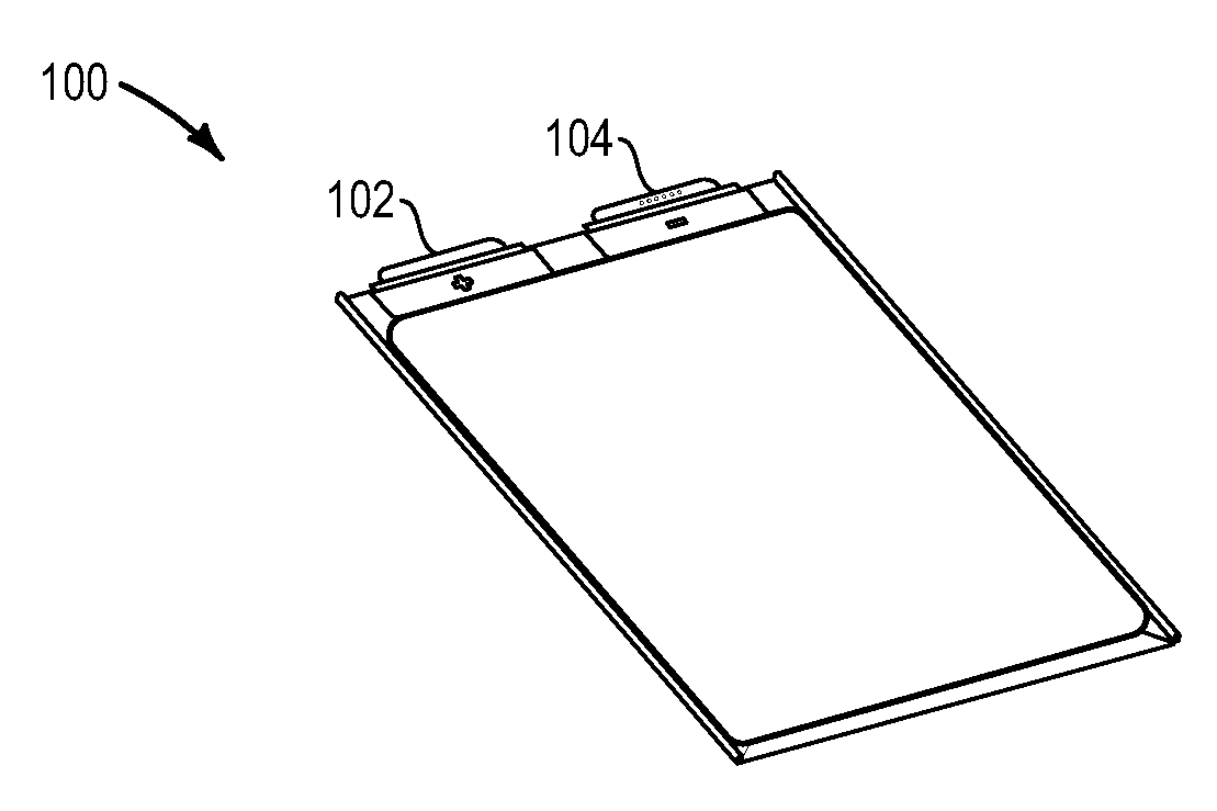
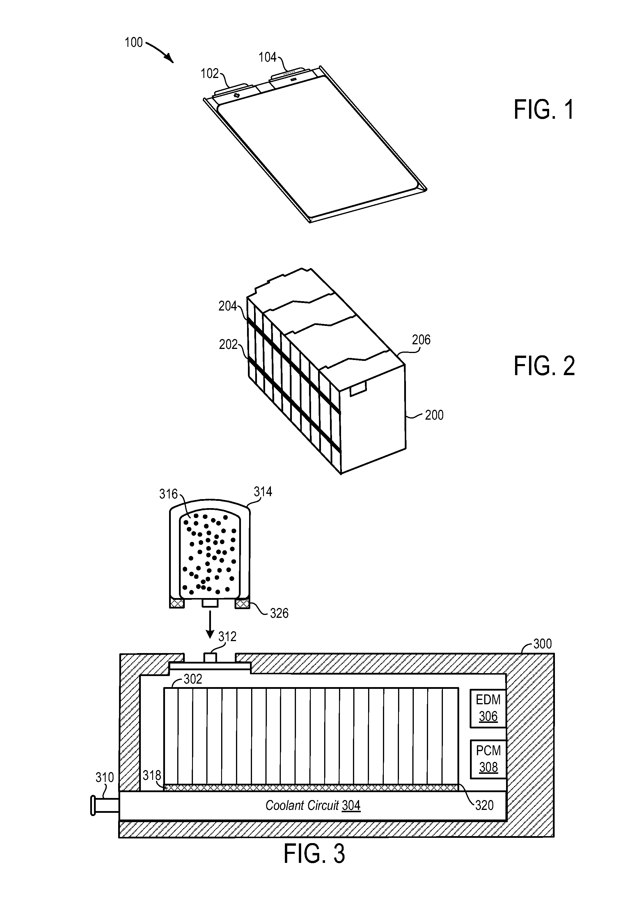
[0022]FIG. 1 shows an exemplary example of a battery cell. Battery cell 100 includes cathode 102 and anode 104 for connecting to a bus (not shown). The bus can route charge from a plurality of battery plates to output terminals of a battery pack.

[0023]Referring now to FIG. 2, an exemplary assembly of a battery cell stack is shown. Battery stack 200 is comprised of a plurality of battery cells. The battery cells are strapped together by bands 202 and 204. Cover 206 provides protection for battery bus bars (not shown) that route charge from the plurality of battery cells to output terminals of a battery pack.

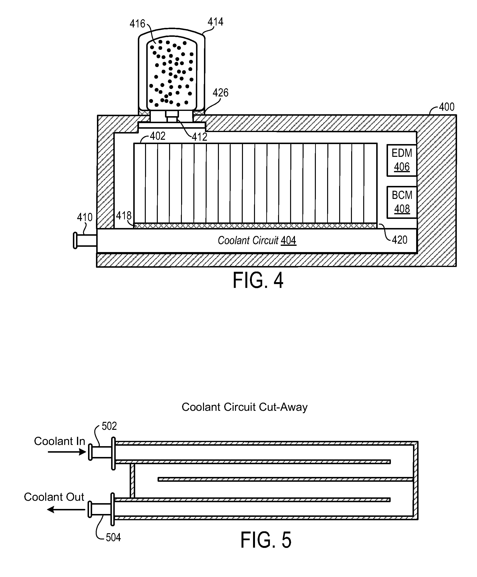
[0024]Referring now to FIG. 3, battery pack 300 contains battery cell stack 302, coolant circuit 304, electrical distribution module (EDM) 306, and battery control module (BCM) 308. Coolant enters the coolant circuit at coolant connector 310. Coolant circuit 304 is in thermal communication with battery cell stack 302 via conductive grease 318 and a cold plate 320 that attaches to ...


PUM

PropertyMeasurementUnit
Massaaaaaaaaaa
Hygroscopicityaaaaaaaaaa
Flow rateaaaaaaaaaa

Abstract

A method for reducing moisture in a battery enclosure is presented. The method may reduce battery degradation during some conditions. In one example, moisture is controlled in a battery enclosure by a desiccant material. In another example, moisture is controlled in a battery enclosure by periodically passing electrical current through a Peltier device.

Description

TECHNICAL FIELD[0001]The present application relates to the field of battery environment management.BACKGROUND AND SUMMARY[0002]To meet increasing power density requirements and environmental constraints manufacturers have recently adopted new compounds for batteries. For example, some batteries contain may contain compounds such as LiCoO2 and LiMn2O4. These compounds may provide high voltage relative to weight. Further, such compounds may be formed into individual battery cells that may be combined to form a battery module. By assimilating a number of battery cells into a module, a high voltage, high capacity energy storage device may be formed. One application for a high voltage, high capacity battery is in a vehicle application in order to extend the vehicle range of the automobile while meeting mass requirements.[0003]However, when some battery compound formulations are exposed to humidity their performance may degrade. In particular, water molecules in air surrounding a battery...

Claims


Application Information

Patent Timeline
IPC IPC(8): H01M10/42H01M50/209
CPCF24F3/1411H01M2/1077H01M2/36H01M10/42Y10T29/4911H01M10/5004H01M10/5093H01M2220/20H01M10/48H01M10/66H01M10/613Y02E60/10H01M50/209
Inventor ALLISON, CHAD JEROMY
Owner A123 SYSTEMS LLC
Why Eureka
Try Eureka