Self-Adjusting Light-Emitting Diode Optical System

a technology of light-emitting diodes and optical systems, which is applied in fixed installation, light and heating equipment, transportation and packaging, etc., can solve the problems of increasing the overall thickness of optic accessories, increasing the gap, and increasing the gap, so as to maximize the usable light output, minimize the effect of wasted light and improved performance and efficiency

Active Publication Date: 2013-10-03
ABL IP HLDG
View PDF9 Cites 60 Cited by
  • Summary
  • Abstract
  • Description
  • Claims
  • Application Information

AI Technical Summary

Benefits of technology

[0006]One advantage of the mounting assembly is directed to allowing an optimum and automatic position adjustment of the light-emitting surface to be achieved based on self-adjustment features. The optimum position adjustment maximizes usable light output and minimizes wasted light under varying conditions, resulting in improvements in performance and efficiency. As such, based on the improvements in efficiency, less power is required to achieve a desired light output. Furthermore, the lower power level allows smaller, simpler heat sinks to be used beca

Problems solved by technology

For example, as optic accessories are added, the overall general thickness of the optic accessories increases, which, in turn, causes the gap to increase.
The larger the number of accessories, the larger the gap.
Similarly, the thicker the accessories, the larger the gap.
Thus, one problem with current fixtures is that, depending on how ma

Method used


Image

  • Self-Adjusting Light-Emitting Diode Optical System
  • Self-Adjusting Light-Emitting Diode Optical System
  • Self-Adjusting Light-Emitting Diode Optical System

Examples


Embodiment Construction

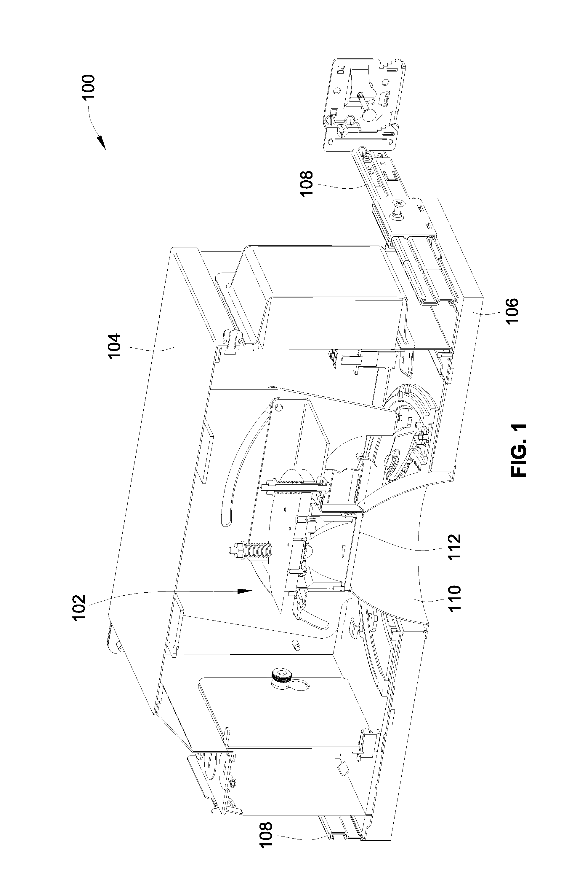
[0021]Referring to FIG. 1, a lighting assembly 100 includes a mounting assembly 102 installed in a ceiling-mounted recessed lighting fixture 104. The lighting fixture 104 is concealed from view by a ceiling 106, and is secured in position on a top side of the ceiling 106 via a plurality of adjustable bars 108, which are typically mounted to structural joists. In another example, the lighting fixture 104 can be mounted in a location that is not concealed by the ceiling and can have a decorative appearance, such as a track lighting fixture.

[0022]A finishing trim 110 is inserted through and mounted flush with the ceiling 106. A top surface of the finishing trim 110 is near a light-emitting surface 112, which, as described in more detail below, remains in the same position regardless of displacements of components in the mounting assembly 102.

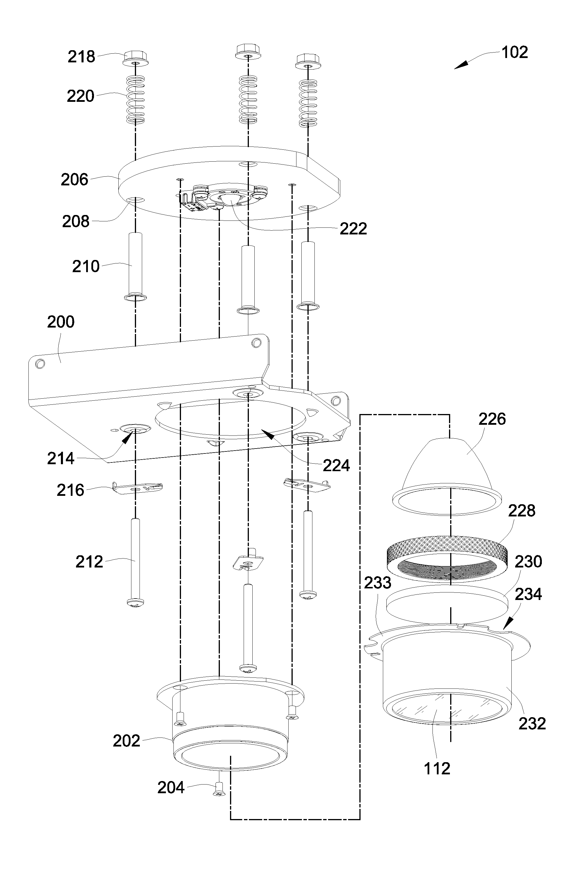
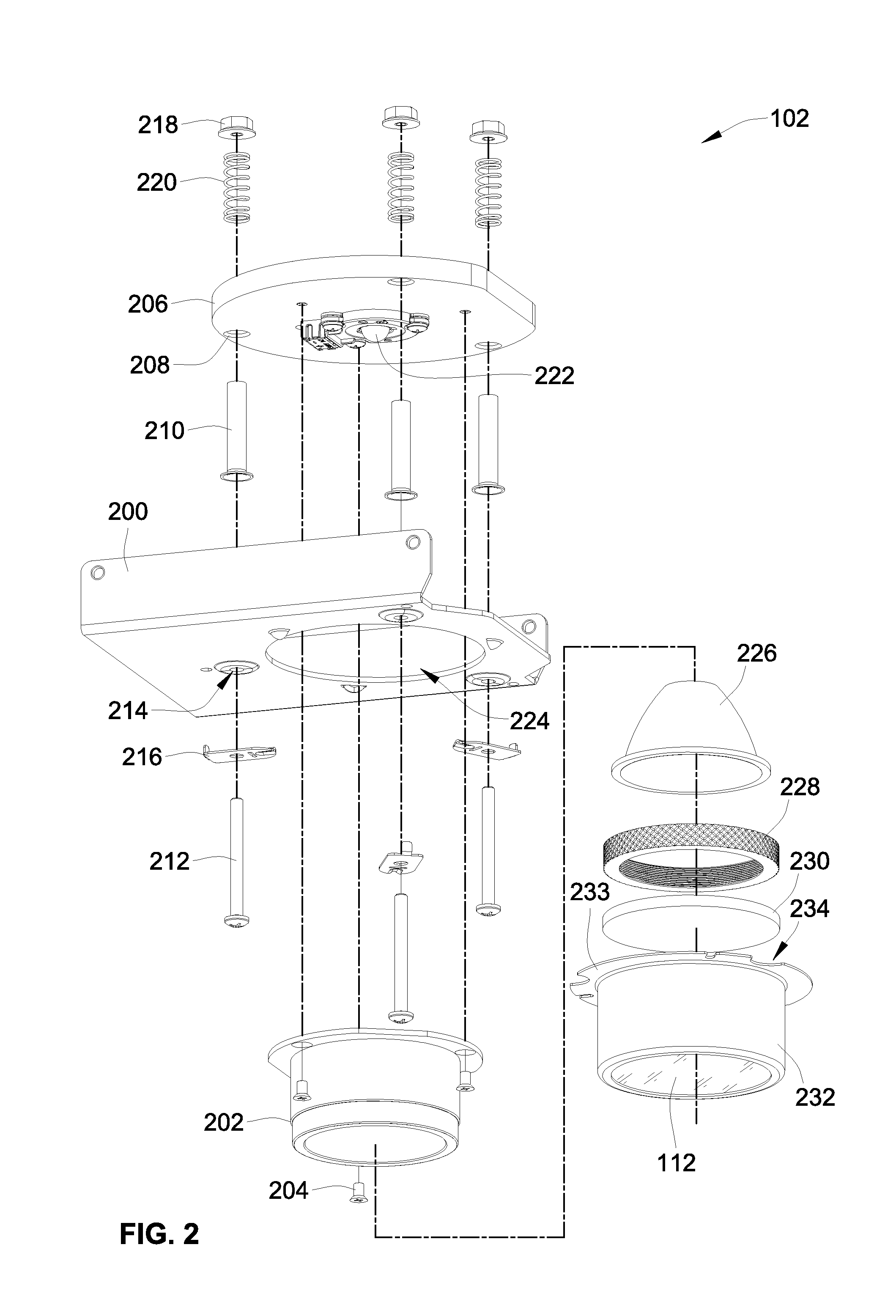
[0023]Referring to FIG. 2, the mounting assembly 102 includes a fixture shield 200 mounted within the lighting fixture 104. An inner optic housing...


PUM


Abstract

A mounting assembly for a lighting fixture includes a fixture shield and an optic housing coupled at least in part to the fixture shield and having a light-emitting surface. The assembly further includes a heat sink movably coupled to the fixture shield in an initial low position, the heat sink being self-adjusting to one or more high positions relative to the fixture shield in direct response to displacement caused by one or more objects contained within the optic housing.

Description

FIELD OF THE INVENTION[0001]This invention is directed generally to lighting systems, and, more particularly, to a self-adjusting mounting system with minimum gap between a light-emitting surface and a finishing trim.BACKGROUND OF THE INVENTION[0002]A standard lighting fixture, such as a recessed lighting fixture, is mounted in a ceiling and includes a mounting assembly having a light-emitting diode light source (“LED”). The LED is mounted to a heat sink, which is in a fixed position relative to a fixture shield of the mounting assembly. The LED emits a light beam transmitted through an optic (which is mounted in an optic housing) into a finishing trim. The face of the optic is generally representative of a light-emitting surface. However, if one or more optic accessories are interposed between the optic housing and the finishing trim, the light-emitting surface is considered to be the face of the last optic accessory through which the light beam passes prior to entering the finishi...

Claims


Application Information

Patent Timeline
IPC IPC(8): F21V5/04F21V29/00F21V29/505
CPCF21V29/004F21V17/162F21S8/026F21V29/70
Inventor FRYZEK, AARON P.WHITTENHALL, JOHN
Owner ABL IP HLDG
Why Eureka
Try Eureka