
Method for Manufacturing Multi-Finger Pinned Root for Turbine Blade Attached to Turbine Rotor and Turbine Blade

a technology of turbine blades and pin insertion holes, which is applied in the direction of blade accessories, machines/engines, waterborne vessels, etc., can solve the problems of high risk of fatigue damage to the inner surface of each pin insertion hole, and achieve the effect of reducing fatigue strength

Inactive Publication Date: 2013-10-03
MITSUBISHI HITACHIPOWER SYST LTD
View PDF31 Cites 7 Cited by
  • Summary
  • Abstract
  • Description
  • Claims
  • Application Information

AI Technical Summary

Benefits of technology

The invention prevents fatigue strength reduction caused by a scratch on the inner surface of a pin insertion hole by making the direction of the scratch and the direction of the resulting tensile stress parallel to each other.

Problems solved by technology

This results in a high risk of fatigue damage to the inner surface of each pin insertion hole.

Method used


Image

  • Method for Manufacturing Multi-Finger Pinned Root for Turbine Blade Attached to Turbine Rotor and Turbine Blade
  • Method for Manufacturing Multi-Finger Pinned Root for Turbine Blade Attached to Turbine Rotor and Turbine Blade
  • Method for Manufacturing Multi-Finger Pinned Root for Turbine Blade Attached to Turbine Rotor and Turbine Blade

Examples


Embodiment Construction

[0024]An embodiment of the present invention will be described below with reference to drawings.

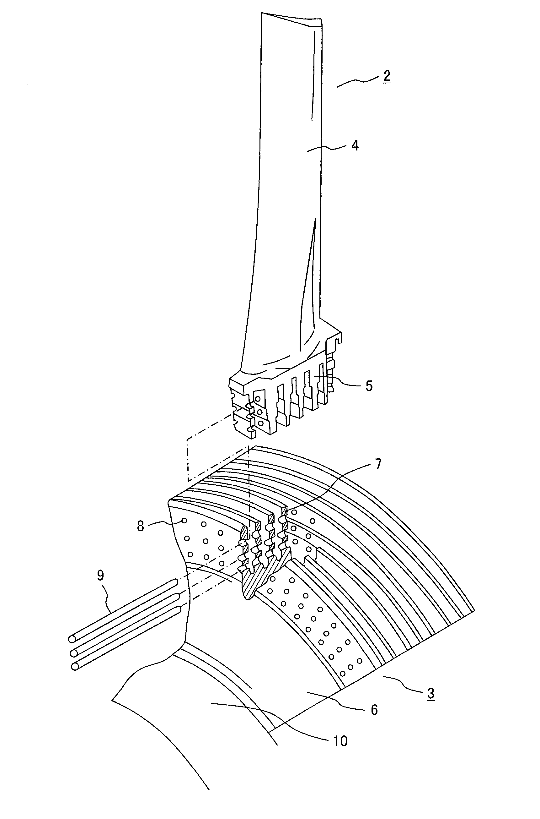
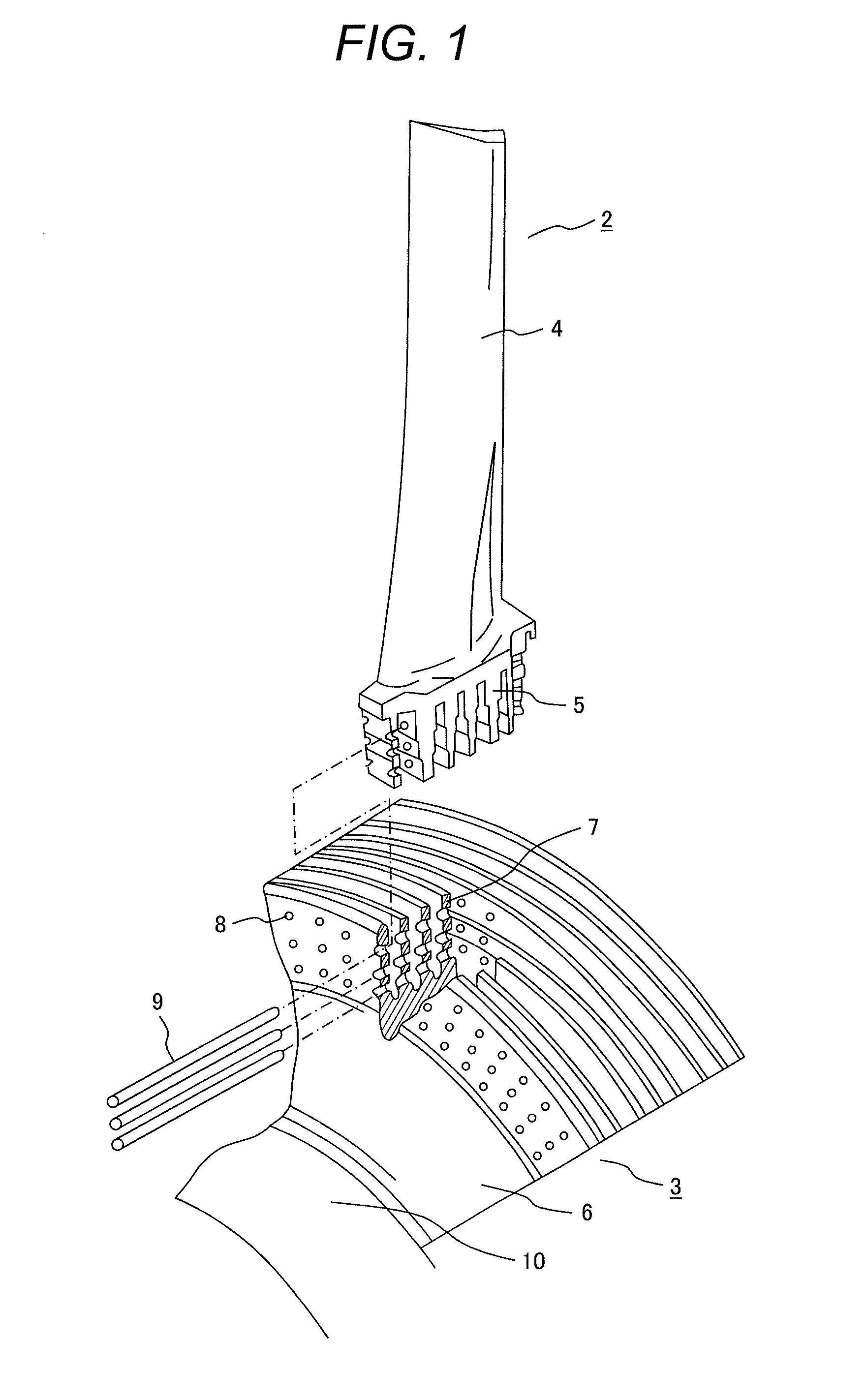
[0025]FIG. 1 is a construction drawing of a turbine blade attachment base. The turbine blade attachment base is comprised of turbine blades 2 and a turbine rotor 3 combined together. Each turbine blade 2 has a blade section 4 which receives a steam flow and converts the energy of the steam flow into a rotational energy for the turbine and a blade fork 5. The turbine rotor 3 has a turbine rotary shaft 10 and a rotor disc 6 provided circumferentially over the turbine rotary shaft 10. The rotor disc 6 has a rotor fork 7 formed thereon.

[0026]The blade fork 5 of the turbine blade 2 and the rotor fork 7 of the turbine rotor 3 are arranged to mesh with each other. The blade fork 5 and the rotor fork 7 have pin insertion holes 8 extending through them in the rotor axis direction. Coupling pins 9 are inserted into the pin insertion holes 8 thereby filling the pin insertion holes 8 and fixing the t...


PUM

PropertyMeasurementUnit
Angleaaaaaaaaaa
Angleaaaaaaaaaa
Angleaaaaaaaaaa

Abstract

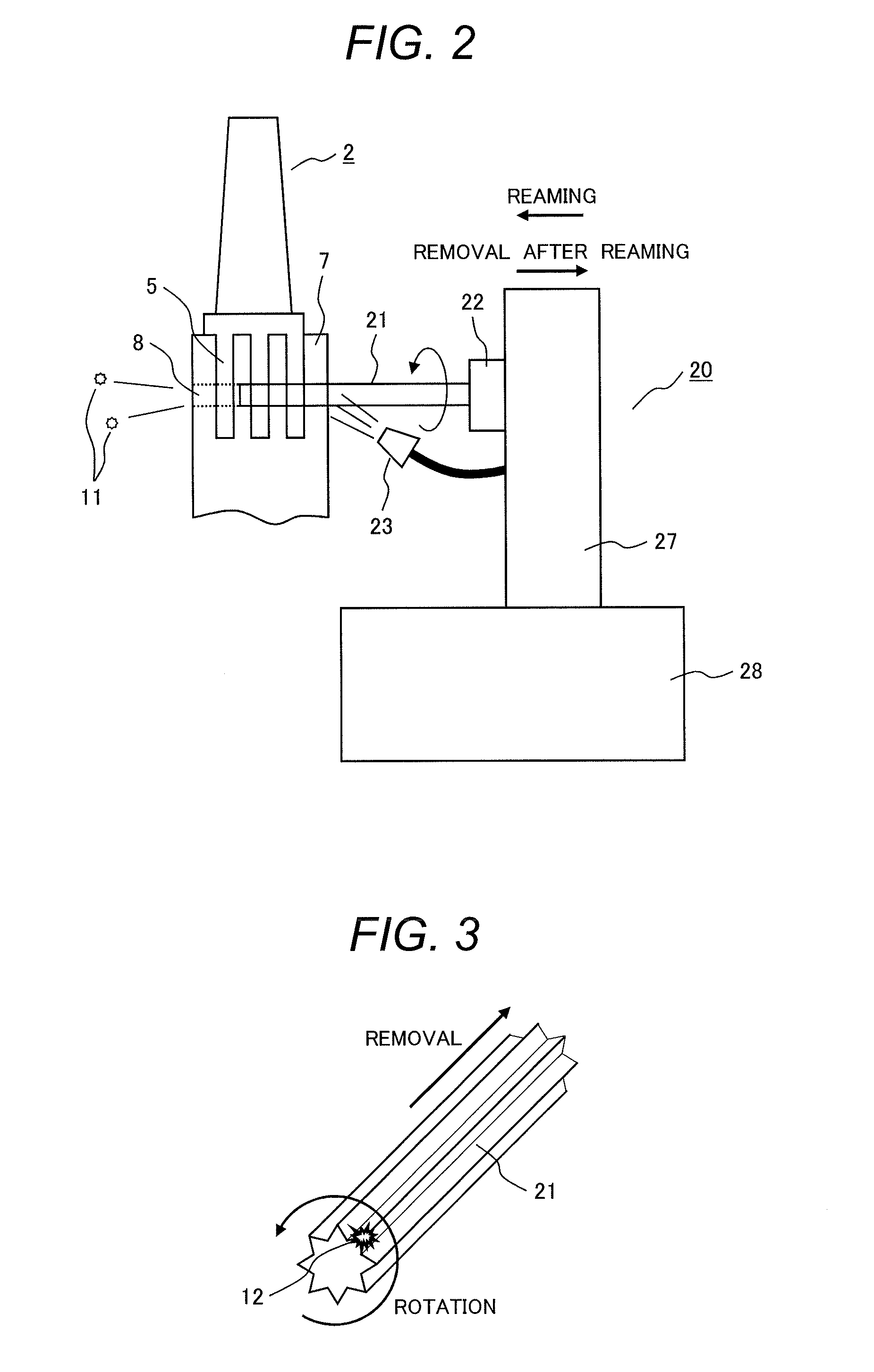
In manufacturing a multi-finger pinned root pin-coupling a turbine blade made of a high-strength material and a rotor disc, a reamer used to ream a pin insertion hole formed through a turbine blade attachment base is removed from the pin insertion hole while being rotated so as to cause a scratch formed by a chip on the inner surface of the pin insertion hole to be inclined with respect to the axial direction of the pin insertion hole. This brings the direction of the scratch on the inner surface of the pin insertion hole and the direction of tensile stress generated on the inner surface of the pin insertion hole adequately close to be parallel to each other. As a result, the fatigue strength reduction caused by the scratch can be inhibited.

Description

TECHNICAL FIELD[0001]The present invention relates a method for manufacturing a multi-finger pinned root for turbine blade attached to a turbine rotor and a turbine blade.CLAIM OF PRIORITY[0002]The present application claims priority from Japanese Patent application serial No. 2012-79867, filed on Mar. 30, 2012, the content of which is hereby incorporated by reference into this application.BACKGROUND ART[0003]A steam turbine for power generation has a rotary shaft referred to as a turbine rotor which is coupled with turbine blades. The turbine blades rotate the turbine rotor by receiving steam power and cause electric power to be generated. When the turbine rotor rotates, a centrifugal force is generated in each turbine blade, and the centrifugal force is supported where the turbine blade is coupled with the turbine rotor. The turbine blade and the turbine rotor can be coupled using, for example, a pin and finger root form, a straddle mount form, or a fir-tree form. A turbine blade ...

Claims


Application Information

Patent Timeline
IPC IPC(8): F01D5/30
CPCF01D5/3023B23D75/00Y10T29/49316F05D2230/10F01D5/3053
Inventor HIRANO, ATSUYATAKAHASHI, MASAAKI
Owner MITSUBISHI HITACHIPOWER SYST LTD
Learn More