
Method and Circuit Arrangement for Transmitting Data Between Processor Modules

a technology of processor modules and circuits, applied in the direction of electric digital data processing, instruments, etc., can solve the problems of comparatively expensive solution of inherently known complex bus systems (complete parallel bus interfaces)

Inactive Publication Date: 2013-10-03
CONTINENTAL TEVES AG & CO OHG
View PDF44 Cites 6 Cited by
  • Summary
  • Abstract
  • Description
  • Claims
  • Application Information

AI Technical Summary

Benefits of technology

The patent describes a flexible and reliable parallel bidirectional digital interface that allows communication between microcontrollers without being affected by bus systems. This leads to easier and less expensive incorporation of external controller functions. The interface allows for the separation of software with different safety levels without the safety level lower application influencing the high safety level application. The invention also simplifies and improves the data throughput and flexibility of the parallel complete bus interfaces. The circuit arrangement includes a conflict avoidance mechanism to prevent data transmission conflicts between interfaces.

Problems solved by technology

This results in these inherently known complex bus systems (complete parallel bus interfaces) being a comparatively expensive solution for the data interchange between integrated electronic chips.

Method used


Image

  • Method and Circuit Arrangement for Transmitting Data Between Processor Modules
  • Method and Circuit Arrangement for Transmitting Data Between Processor Modules
  • Method and Circuit Arrangement for Transmitting Data Between Processor Modules

Examples


Embodiment Construction

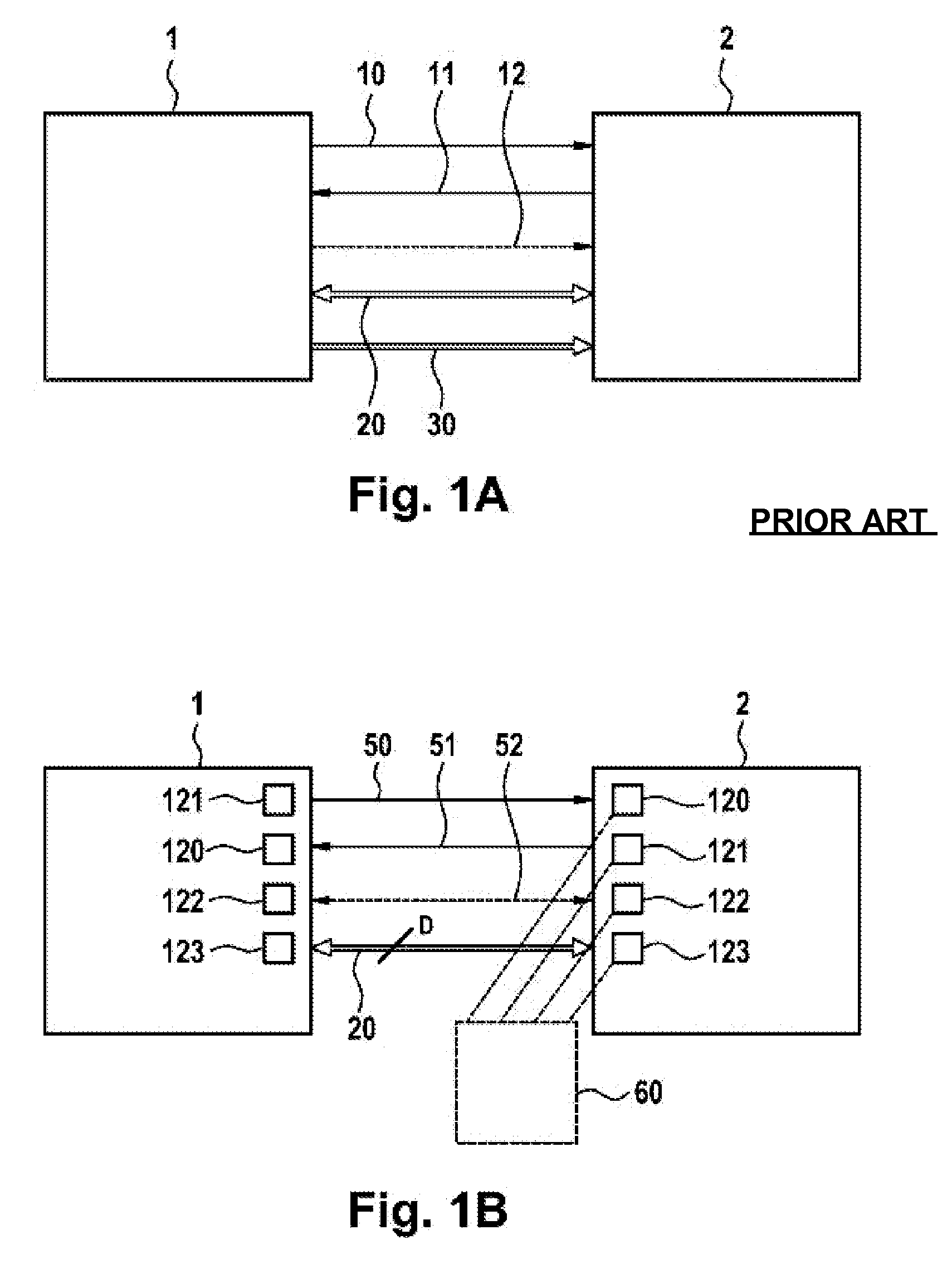
[0040]In FIG. 1A (prior art), microcontroller (μC) 1 is always operated in master mode and therefore determines the addresses for read and write access operations in the microcontroller 2. The microcontroller 2 is always operated in slave mode. Address lines 30 are laid unidirectionally from the master to the slave. Data lines 20 are bidirectional. The master microcontroller 1 sends control signals 10 to the slave microcontroller 2 in order to stipulate the meaning of the data signals. The slave microcontroller 2 sends response signals 11 to the microcontroller 1. For synchronized data transmission, synchronization signals 12 are also required.

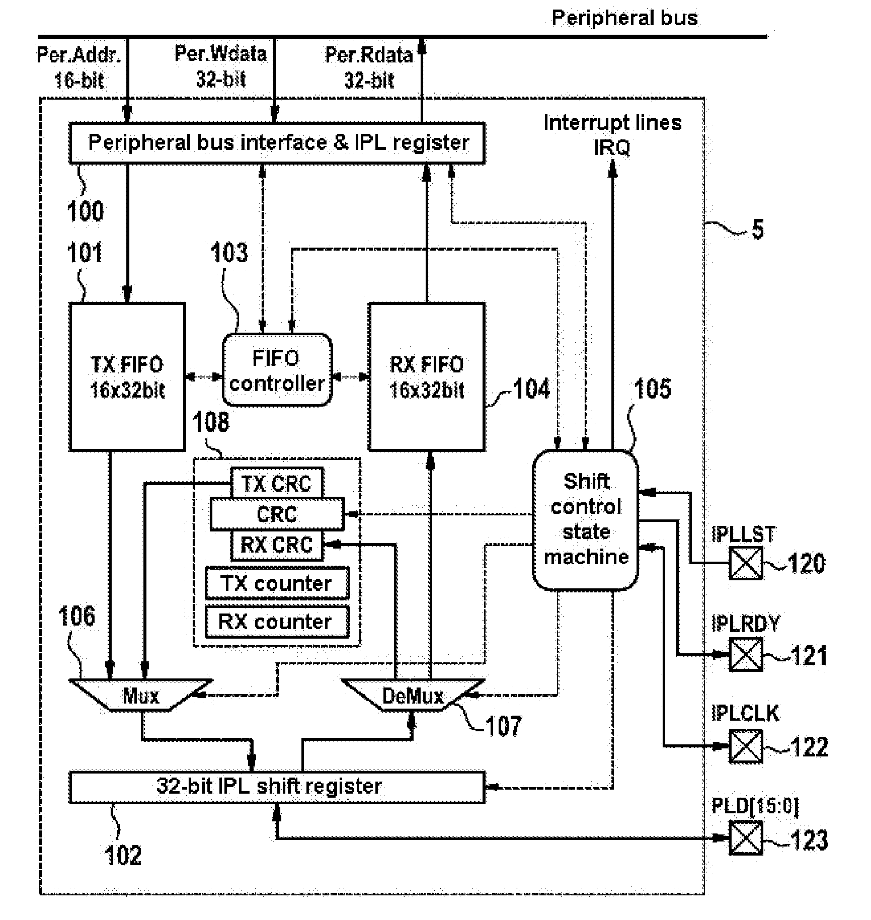
[0041]FIG. 1B shows an example of a design—simplified according to the invention—for a parallel bus interface, which is also called a digital bidirectional parallel interface or an IPL interface. Address lines 30 (FIG. 1A) are not present. Each microcontroller (μC) 1 or 2 has the four pins 120 to 123, which are also shown in FIG. 3. Pin 121 of...


PUM


Abstract

The invention relates to a circuit arrangement for forming a digital interface comprising a digital data bus, which exchanges data when microprocessor systems are connected. The data exchange can be effected bidirectionally. On transmission of data the circuit arrangement generates as bus master a bus clock speed and operates on receipt of data as a bus slave in accordance with the received clock signal. The circuit arrangement comprises at least one FIFO memory for receiving data.

Description

CROSS-REFERENCE TO RELATED APPLICATIONS[0001]This application claims priority to German Patent Application Nos. 10 2010 043 929.0, filed Nov. 15, 2010; 10 2011 007 437.6, filed Apr. 14, 2011; and PCT / EP2011 / 063574, filed Aug. 5, 2011.FIELD OF THE INVENTION[0002]The present invention relates to a method and a circuit arrangement for data transmission between processor chips.BACKGROUND OF THE INVENTION[0003]Motor vehicles make widespread use of electronic control units (ECUs) for a wide variety of vehicle functions. In this context, there are control units (ECUs) for safety-critical applications, e.g. for the brakes, and for nonsafety critical applications, e.g. comfort functions such as air conditioning, seat heating, etc. For safety reasons, control units having differently classified safety requirements (ASIL levels) are usually implemented by separate, standalone electronic control units which are able to communicate with one another via digital vehicle data bus connections which ...

Claims


Application Information

Patent Timeline
Patent Type & Authority Applications(United States)
IPC IPC(8): G06F13/364
CPCG06F13/364G06F13/4265G06F13/38G06F13/42
Inventor WEGENER, BASTIANKABULEPA, LUKUSA DIDIERHARTMANN, RALFBITSCH, CHRISTIAN
Owner CONTINENTAL TEVES AG & CO OHG
Learn More