Cable for use in concentrated solar power installation

a concentrated solar power and cable technology, applied in the field of cables, can solve the problems of poor shield protection performance, insufficient strength, adversely affecting the flexibility and workability of cable installation, etc., and achieve the effect of good bending performan

Inactive Publication Date: 2013-10-10
XU HAILONG +2
View PDF30 Cites 11 Cited by
  • Summary
  • Abstract
  • Description
  • Claims
  • Application Information

AI Technical Summary

Benefits of technology

[0008]In view of the above, the object of the present utility model is to provide a cable which not only has good bending performance (i.e. with small minimum bending radius), but also is

Problems solved by technology

A cable haying a shield of these structures is defective mainly in that, the minimum bending radius of the cable is large, usually more than 100 mm, which adversely affects the flexibility and workability in cable installation.
In addition, the cable is often installed above ground or directly buried in earth surface region in unfavor

Method used


Image

  • Cable for use in concentrated solar power installation
  • Cable for use in concentrated solar power installation
  • Cable for use in concentrated solar power installation

Examples


Embodiment Construction

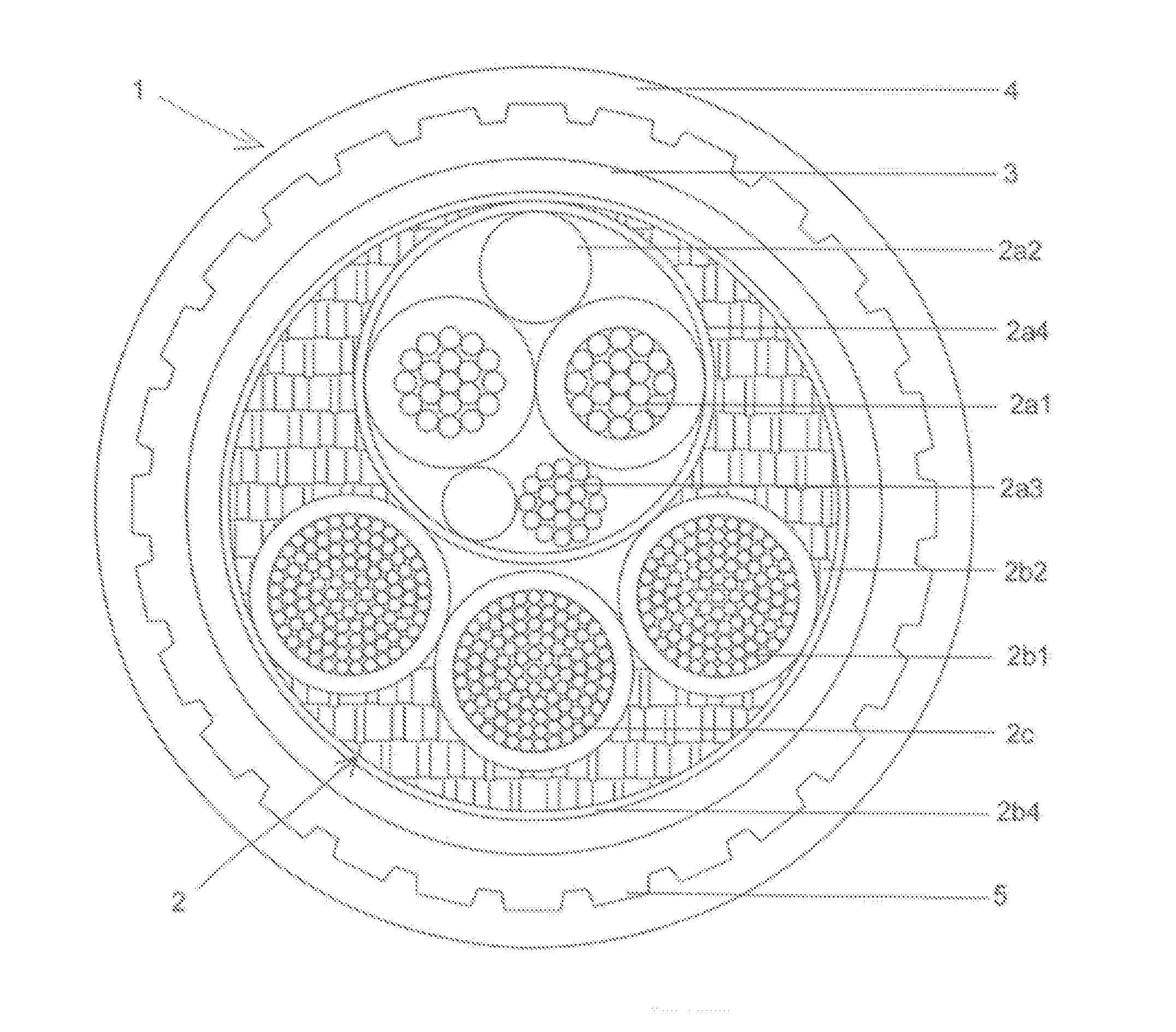
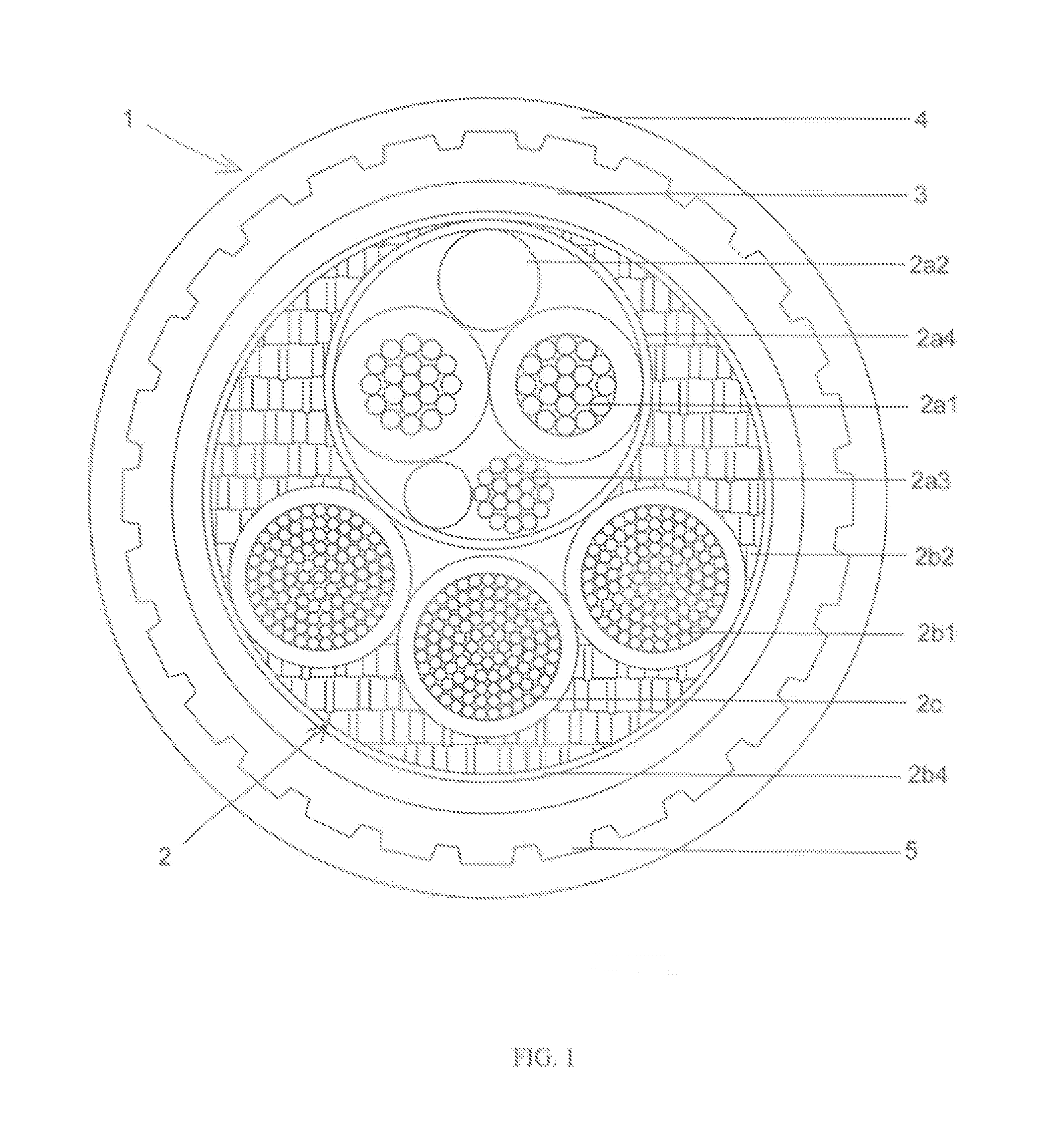
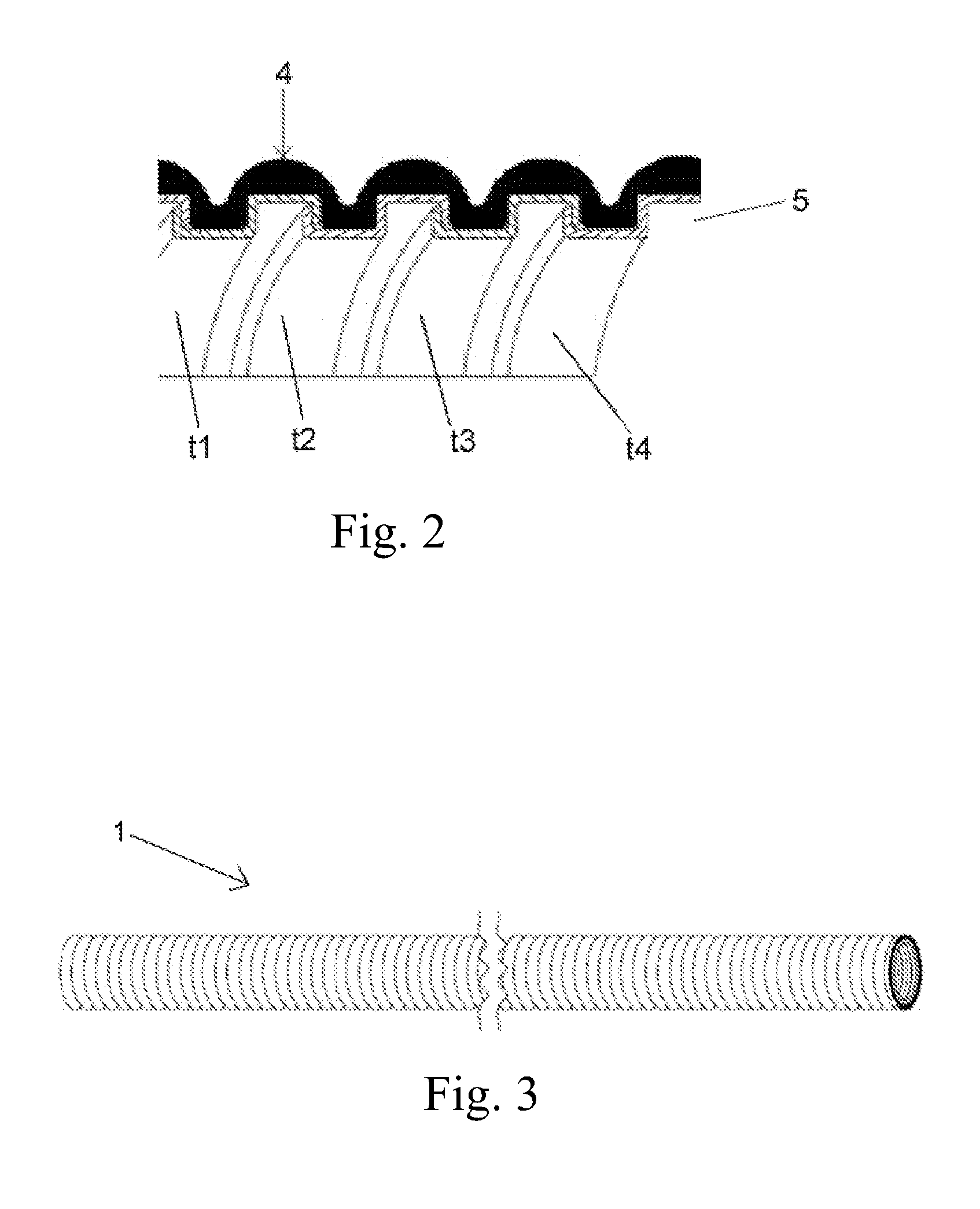
[0021]FIG. 1 shows the cross sectional structure of the cable 1 according to an embodiment of the present utility model. The cable 1 comprises a core 2 for transmitting signals and power, an inner jacket 3 enclosing the core 2, an outer jacket 4 enclosing the inner jacket 3, and a shield 5 disposed between the inner and outer jackets.

[0022]The core 2 may include a first component for transmitting signals and a second component for transmitting power. As shown in FIG. 1, the first component may include, for example, conductors 2a1 with insulation, fillers 2a2, drain wires 2a3 and a covering 2a4; the second component may include, for example, conductors 2b1 with insulation, optional fillers 2b2 and a covering 2b4, wherein the fillers 2b2 spread over the inner space of the covering 2b4; and the second component surrounds the first component. Optionally, the core 2 may further include drain wires 2c with insulation, which are arranged within the second component and relate to the power ...


PUM


Abstract

A cable (1) in particular for use in a concentrated solar power installation is provided, is provided with a core (2) for transmitting signals and/or power, an inner jacket (3) enclosing the core, an outer jacket (4) enclosing the inner jacket, and a shield (5) disposed between the inner and outer jackets. The shield is configured as a flexible conduit. A concentrated solar power installation comprising the cable is also provided.

Description

RELATED APPLICATION[0001]This application claims the benefit of priority from Chinese Patent Application No. CN 2011 20441739.8, filed on Nov. 9, 2011, the entirety of which is incorporated by reference.BACKGROUND[0002]1. Field of the Invention[0003]The present utility model relates to a cable, and particularly to a cable for transmitting signals and / or power in a concentrated solar power (CSP) installation.[0004]2. Description of the Related Art[0005]A CSP installation concentrates sunlight by means of a plurality of light concentrated reflectors (e.g. mirrors), and heats up gaseous or liquid medium (such as oil or water) by the concentrated sunlight; then thermal energy of the medium is converted into mechanical energy which is finally converted into electric power.[0006]For a CSP installation, in order to regulate the reflection angle of the light concentrated reflectors, it is necessary to supply the reflectors with signals and power such that the reflectors can move and thereby...

Claims


Application Information

Patent Timeline
IPC IPC(8): H01B7/17
CPCH01B7/17F24J2/46H02G3/0475H01B7/207H01B7/04F24S80/00
Inventor XU, HAILONGLI, MILIN, XIONGWEN
Owner XU HAILONG
Why Eureka
Try Eureka