Air turbine handpiece

a handpiece and air turbine technology, applied in the field of handpieces of air turbines, can solve the problems of generating negative pressure in the turbine room, contaminant inhalation of patient saliva and blood etc., and inhalation of ambient air, so as to prevent cross infection between patient and operator or among patients, prevent negative pressure from being generated efficiently, and prevent foreign material from being inhaled

Inactive Publication Date: 2013-10-10
YOSHIDA DENTAL MFG
View PDF4 Cites 12 Cited by
  • Summary
  • Abstract
  • Description
  • Claims
  • Application Information

AI Technical Summary

Benefits of technology

[0043]In the air turbine handpiece according to the present invention, one end of the reflux duct is communicate with the exhaust tube and the other end of the reflux duct is opened to the turbine room near the air supply port of the air supply duct, so that the exhaust is returned directly to the portion where the negative pressures are caused easily most in the turbine room, and the negative pressure can be prevented from being generated efficiently by the refluxed exhaust. As a result, the foreign material can be prevented from being inhaled in the handpiece when the negative pressure is generated in the air turbine handpiece, and the cross infection between patient and operator or among patients can be prevented from being generated through the air turbine handpiece. Also, in the air turbine handpiece according to the present invention, the reflux duct communicated with the exhaust duct is provided near the air supply port of the air supply duct, and the exhaust is returned directly to the portion of the turbine room where the negative pressures are caused most in turbine room, so that the negative pressure can be prevented from being generated by the refluxed exhaust. Furthermore, in the case of using the air turbine handpiece, the reflux air supplied from the reflux duct is jetted toward the turbine blade together with the supplied air of the original driving force, so that the secondary effect that the rotation drive of the turbine blade can be helped, can also be obtained. Moreover, the constitution of the reflux duct is simple, and the machining is also easy, so that the air turbine handpiece can be provided with low price. As a result, present invention has an advantage that the cross infection between patient and operator or among patients can be prevented from being generated through the conventional air turbine handpiece. Particularly, also, according to the present invention, a value in which an aperture at the reflux exit of the reflux duct is divided by an aperture in the air supply port of the air supply duct, is set to one or less (≧1), so that during use of the air turbine handpiece, in addition to the air charge jetted from the air supply duct toward the turbine blade, the supply quantity of air increases by the reflux exhaust supplied to the negative pressure generation portion of turbine room through the reflux duct, and thus the rotation driving force of the air turbine handpiece is reinforced and the energy-saving effect can be obtained. Moreover, the constitution of the reflux duct according to the present invention is simple, and the machining is easy, so that the air turbine handpiece can be provided with the low price.

Problems solved by technology

However, even if the supply of the pressurized air is intercepted, the turbine blade continues the inertia rotation by own inertia force so that the air in the turbine room is exhausted by the inertia rotation, resulting in a generation of negative pressure therein.
Moreover, the air in the turbine room is communicated with ambient air through the gap in surroundings of rotation axis so that interior of the turbine room becomes a negative pressure, resulting in generation of negative pressure in the turbine room.
Moreover, the air in the turbine room is communicated with the ambient air through the gap in surroundings of rotation axis, so that the interior of the turbine room becomes a negative pressure, resulting in a inhalation of ambient air in the turbine room, and resulting in a inhalation of contaminant such as saliva and blood etc. of patient together with the inhalation of ambient air.
As a result, the interiors of the joint metal fittings and the feed and exhaust hoses which are connected to the interior of the head portion and / or the handpiece, are polluted.
Moreover, in addition to the above constitution, the space between the turbine blade and upper and lower internal wall surface of the chamber is made narrow, particularly, an increase in the torque that caused to rotate the cutting tool.

Method used


Image

  • Air turbine handpiece
  • Air turbine handpiece
  • Air turbine handpiece

Examples


first embodiment

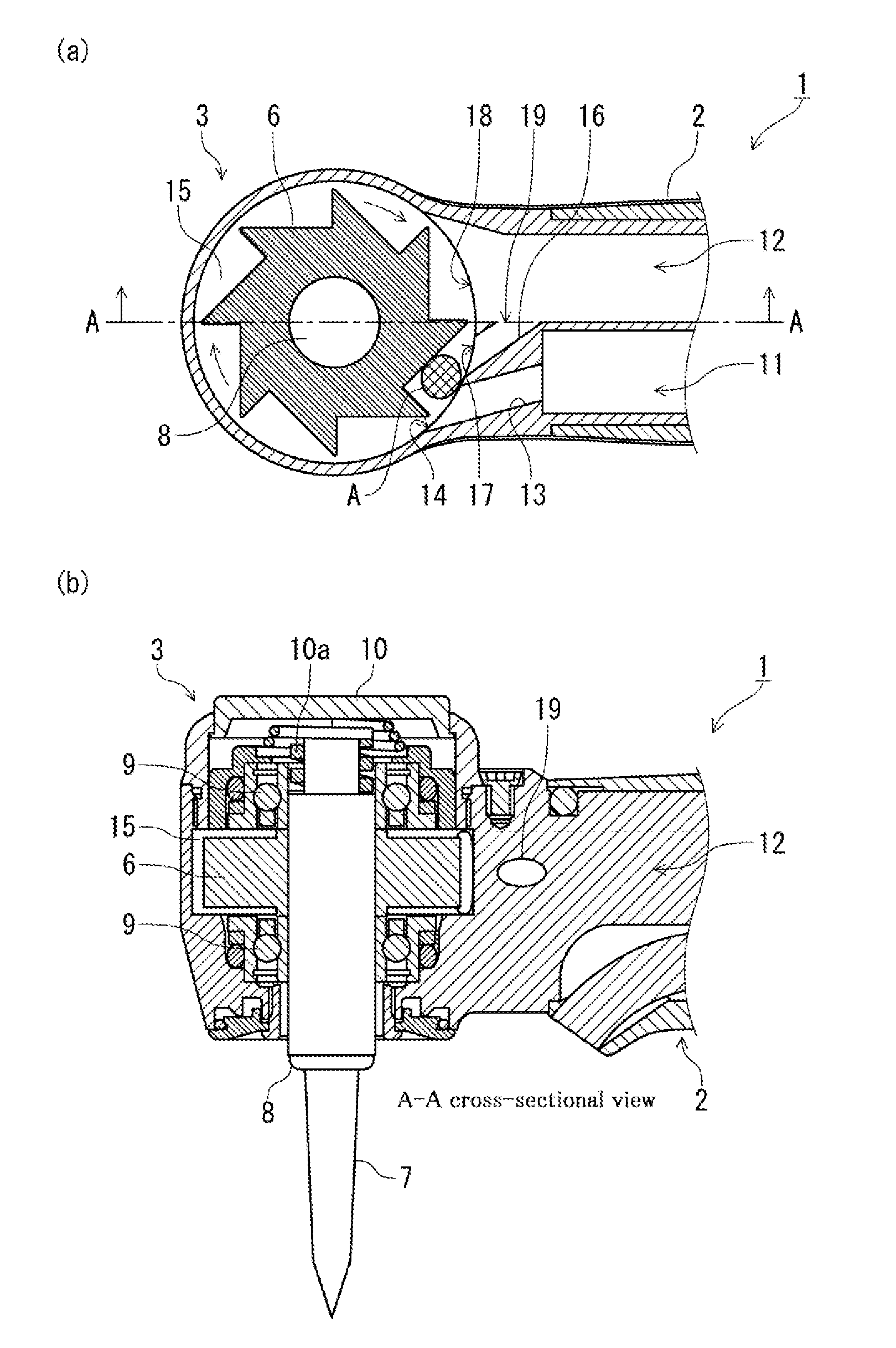
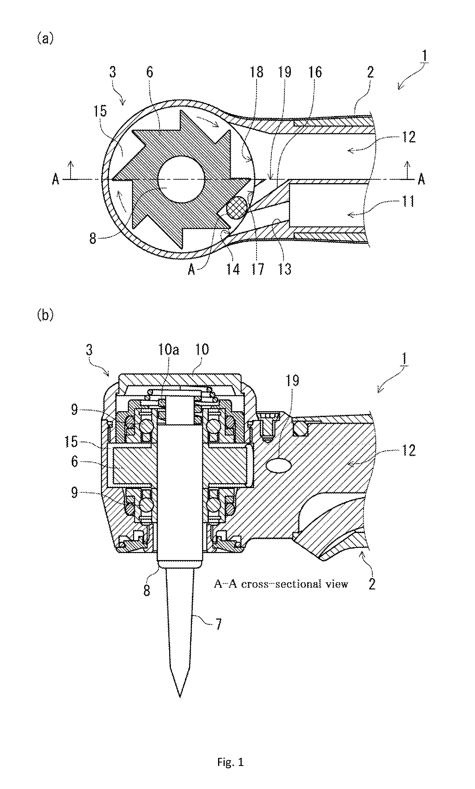
[0054]As shown in the FIG. 7, an air turbine handpiece 1 of this embodiment that applies the present invention comprises a neck portion 2 grasped by an operator, a head portion 3 installed consecutively to the tip side of the neck portion 2, and a grip portion 4 installed consecutively behind the neck portion 2, and a hose 5 with built-in feed pipe and exhaust pipe (not shown) is connected with the rear end of the grip portion 4.

[0055]As shown in FIG. 1, a turbine room 15 is formed in the interior of the head portion 3 of the air turbine handpiece 1, and a turbine blade 6 is fixed to a chuck 8 that supports a tool 7, in interior of the turbine room 15, and is rotatably supported by ball bearings 9 of one pair of upper and lower sides through the chuck 8. Moreover, on the upper end of the chuck 8, the tool 7 is constructed detachably by compressing a pushbutton 10 against energisation of a spring 10a. Furthermore, at the side of the neck portion 2 of the head portion 3, an air supply...

second embodiment

[0063]FIG. 5 shows second embodiment of an air turbine handpiece of the present invention. As shown in FIGS. 5 (a) and (b), in an air turbine handpiece 1 according to the present embodiment 2, is constructed in such a manner that instead of the fact that the reflux exit 17 of the reflux duct 16 is opened to the air supply port 14 near the air supply duct 11 in the above first embodiment, the reflux exit 21 of the reflux duct 20 communicated with the reflux entry 22 opened to the exhaust duct 12, is opened to near the air supply port 14 in the nozzle 13 of the air supply duct 11 near.

[0064]In this case, when the supply of air from the air supply duct 11 is stopped, as shown in FIG. 6 by an arrow (b), the exhaust air exhausted by the inertia rotation of turbine blade 6 is entered in the nozzle 13 from the reflux exit 21 through the reflux entry 22 of reflux duct 20, and is flowed to the area A of the turbine blade 6. As a result, although in the case of present embodiment, the operati...


PUM


Abstract

An air turbine handpiece having: a head portion with built-in free turbine blade, a neck portion installed consecutively with the head portion and grasped by an operator, a grip portion installed consecutively with the neck portion, an air supply duct for driving the turbine blade, and an exhaust duct for exhausting the air. The exhaust duct is provided with a reflux duct, open at one end to the exhaust duct, and open at the other end to the turbine room as the exhaust exit, a value in which an aperture at the reflux exit of the reflux duct is divided by an aperture in the air supply port of the air supply duct, becomes one or less, and the reflux exit of the reflux duct is opened to the turbine room near the air supply port between the air supply port and the exhaust exit.

Description

TECHNICAL FIELD[0001]The present invention relates to an air turbine handpiece used for dental therapeutics etc., particularly, an air turbine handpiece capable of improving the rotation efficiency of the turbine, in which when the turbine stops in case of ending use of the kind of air turbine handpiece, generation of negative pressure due to inertia rotation of the turbine blade is prevented in the turbine room and the reflux duct as a negative pressure prevention means is used as the promotion means of driving force at the time of driving the turbine again.BACKGROUND ART[0002]When the drive of the turbine is ended, the conventional air turbine handpiece intercepts the supply of the pressurizing air being as driving medium. However, even if the supply of the pressurized air is intercepted, the turbine blade continues the inertia rotation by own inertia force so that the air in the turbine room is exhausted by the inertia rotation, resulting in a generation of negative pressure ther...

Claims


Application Information

Patent Timeline
Patent Type & Authority Applications(United States)
IPC IPC(8): F01D25/00
CPCA61C1/057F01D25/00A61C1/12
Inventor HASEGAWA, TAKESHI
Owner YOSHIDA DENTAL MFG
Why Eureka
Try Eureka