Method and system for controlling a powerplant during low-load operations

a powerplant and low-load technology, applied in steam engine plants, machines/engines, mechanical equipment, etc., can solve problems such as undesirable emissions and/or pollutants in combustion processes, and achieve the effect of increasing the turndown range of the powerplan

Inactive Publication Date: 2013-10-17
GENERAL ELECTRIC CO
View PDF20 Cites 87 Cited by
  • Summary
  • Abstract
  • Description
  • Claims
  • Application Information

AI Technical Summary

Problems solved by technology

The combustion process creates undesirable emissions and / or pollutants, such as Carbon Monoxide (CO) and Oxides of Nitrogen (NOx).

Method used


Image

  • Method and system for controlling a powerplant during low-load operations
  • Method and system for controlling a powerplant during low-load operations
  • Method and system for controlling a powerplant during low-load operations

Examples


first embodiment

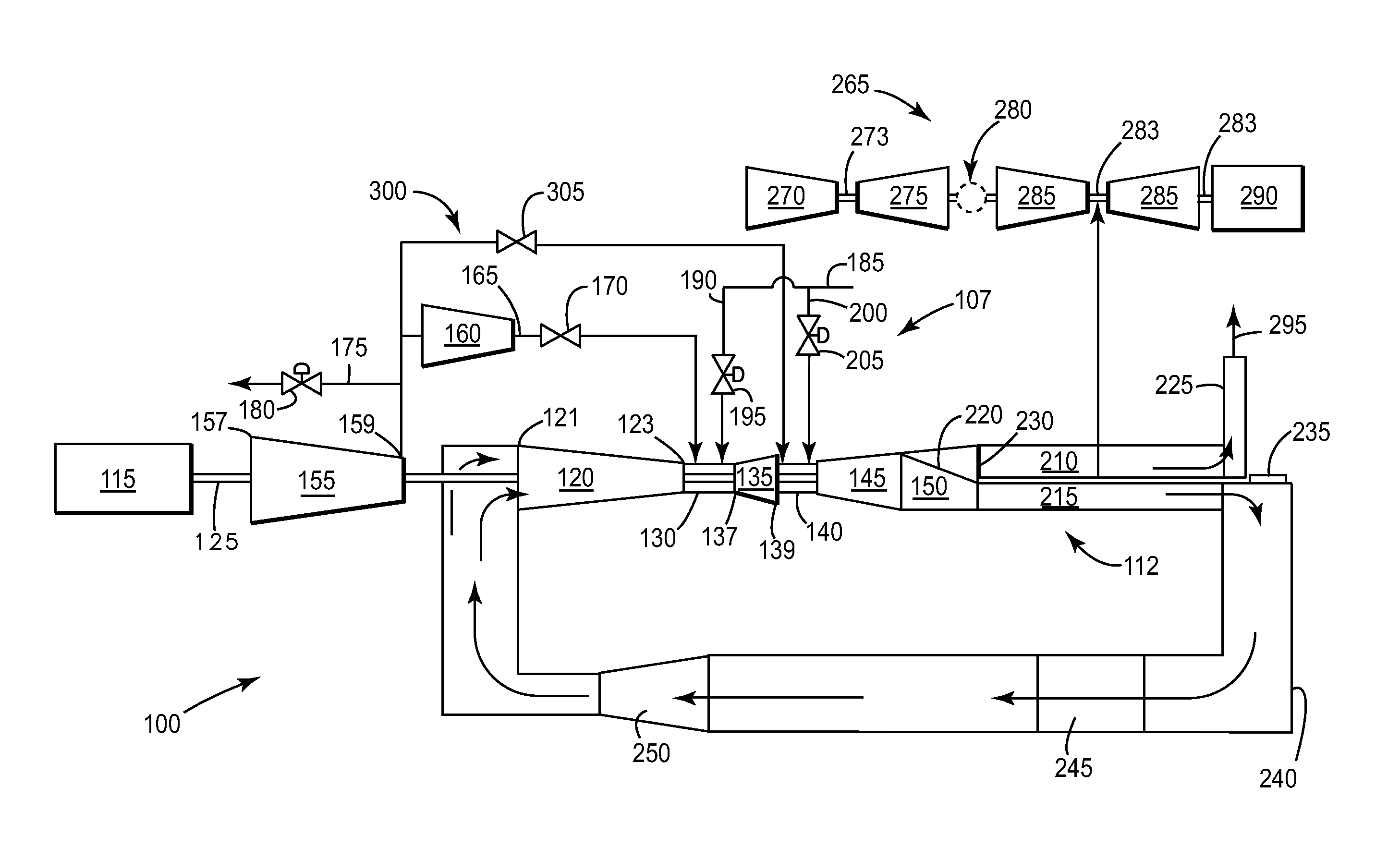
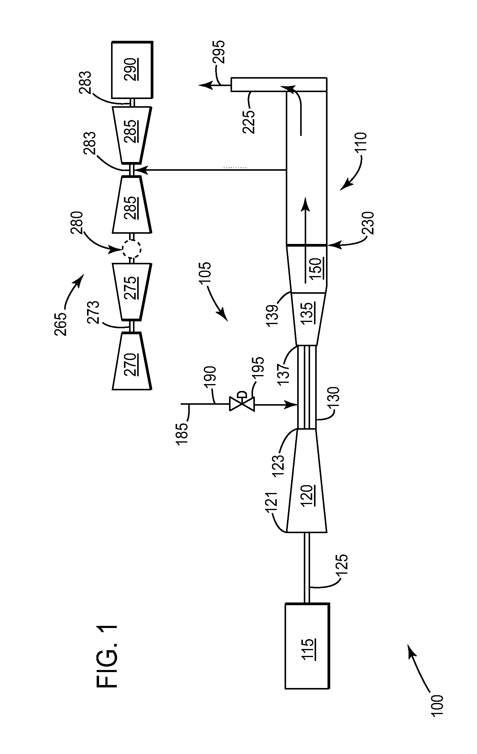
[0023]Referring now to the FIGS, where the various numbers represent like components throughout the several views, FIG. 1 is a simplified schematic of a standard gas turbine operating in an open-cycle mode, illustrating the present invention.

[0024]In FIG. 1, a site 100 includes: a gas turbine 105, operatively connected to a heat recovery steam generator (HRSG) 110, a load 115, a steam turbine 265, and a load 290. The gas turbine 105 may include a GT compressor 120 having a compressor inlet 121 and a compressor outlet 123. The GT compressor 120 ingests ambient air through the compressor inlet 121, compresses and then discharges the compressed air through the compressor outlet 123. The GT compressor 120 may then deliver the compressed airstream to the primary combustion system 130.

[0025]The gas turbine 105 may also include a primary combustion system 130 that receives: the compressed airstream; a fuel supply 185, comprising a first fuel conduit 190 and first fuel valve 195. The primar...
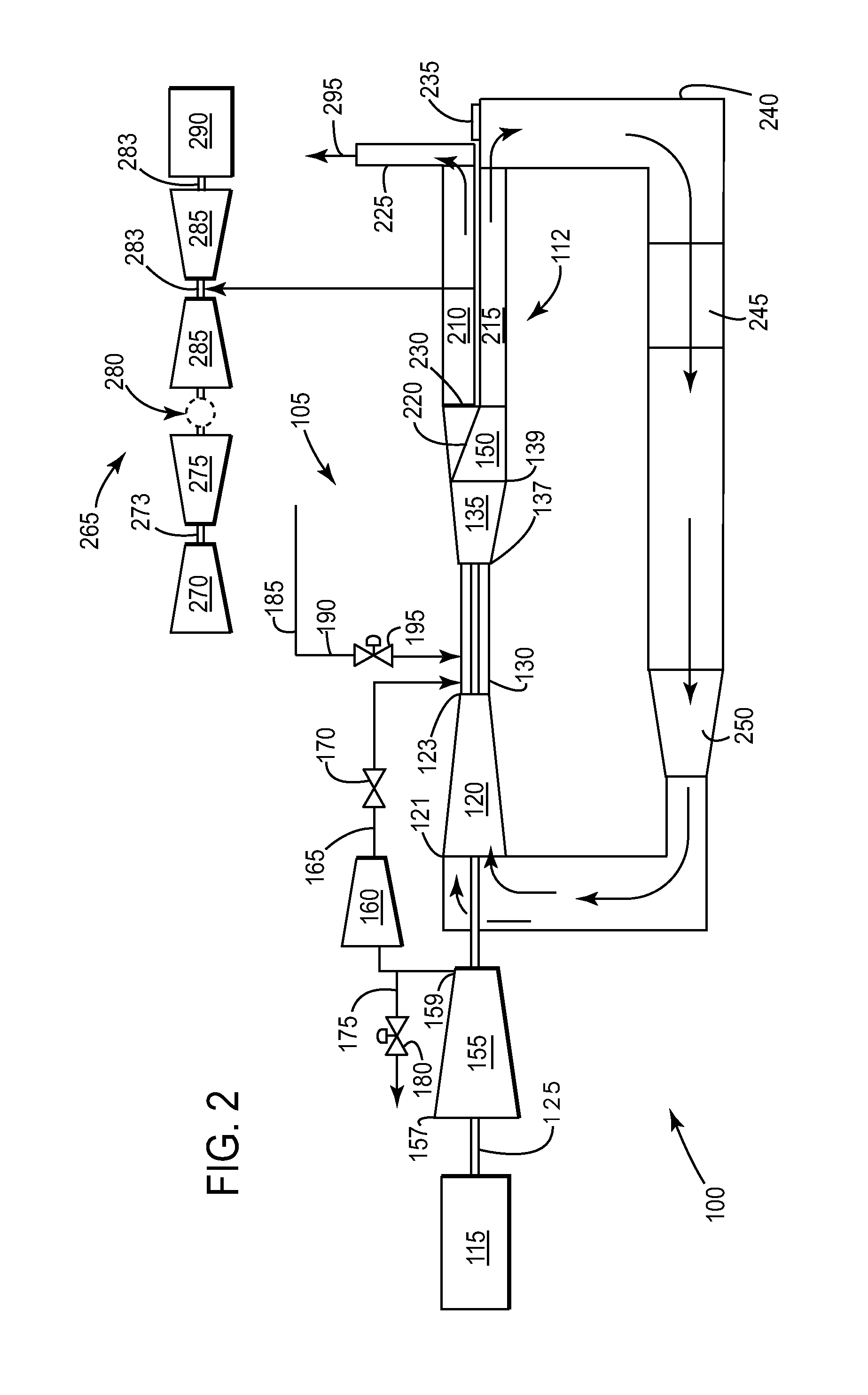
second embodiment

[0038]Referring again to the figures, FIG. 2 is a simplified schematic of a standard gas turbine 105 operating in a closed-cycle mode, illustrating the present invention. In FIG. 2, a site 100 includes: a gas turbine 105, operatively connected to a split-HRSG 112, a load 115, a steam turbine 265, and a load 290. The gas turbine 105 may include a GT compressor 120 having a compressor inlet 121 and a compressor outlet 123. The GT compressor 120 ingests recirculated exhaust gases (hereinafter “working fluid”) received from the EGR system 240, compresses the working fluid, and discharges the compressed working fluid through the compressor outlet 123. The gas turbine 105 may include an oxidant compressor 155 that ingests an oxidant, such as ambient air, through an ac_inlet 157, compresses the same, and discharges the compressed air through the ac_outlet 159. The oxidant compressor 155 may deliver the compressed airstream to the primary combustion system 130 through an airstream conduit 1...


PUM


Abstract

The present invention provides a system and method of operating a combined-cycle powerplant at part-load without shutting down an HRSG and steam turbine. The present invention may apply to a powerplant operating in an open-cycle mode. The present invention may also apply to a powerplant operating in a closed-cycle mode.

Description

BACKGROUND OF THE INVENTION[0001]This application is related to [GE Docket 249101], [GE Docket 249104], [GE Docket 250883], [GE Docket 250998], [GE Docket 254241], [GE Docket 256159], [GE Docket 257411], and [GE Docket 258552] filed concurrently herewith, which are fully incorporated by reference herein and made a part hereof.[0002]The present application relates generally to a combined cycle powerplant, and more particularly to, a system and method for operating the powerplant when base-load output is not desired.[0003]In an air-ingesting turbomachine, compressed air and fuel are mixed and combusted to produce a high energy fluid (hereinafter “working fluid”) that is directed to a turbine section. The working fluid interacts with turbine buckets to generate mechanical energy. These buckets rotate a shaft coupled to the load, such as an electrical generator. The shaft rotation induces current in a coil electrically coupled to an external electrical circuit. In the case where the tur...

Claims


Application Information

Patent Timeline
Patent Type & Authority Applications(United States)
IPC IPC(8): F01K23/10F02C9/00F02C7/228F02C3/04F02C3/34
CPCF02C3/107F02C6/18F02C9/00F05D2220/72Y02E20/16
Inventor WICHMANN, LISA ANNEBUTKIEWICZ, JEFFREY JOHNSIMPSON, STANLEY FRANK
Owner GENERAL ELECTRIC CO
Why Eureka
Try Eureka