Position indicator

a technology of position indicator and position indicator, which is applied in the direction of mechanical measuring arrangement, instruments, and using mechanical means, can solve the problems of bending into bananas, inability to properly use conventional pen-type position indicators, etc., and achieves the effects of preventing (internal) stress, improving manufacturing ease, and improving manufacturing eas

Active Publication Date: 2013-10-17
WACOM CO LTD
View PDF0 Cites 42 Cited by
  • Summary
  • Abstract
  • Description
  • Claims
  • Application Information

AI Technical Summary

Benefits of technology

[0034]In addition, since the holder only has to be accommodated in the cylindrical chassis after the core body, the one or more pressure-sensitive components, and the printed wiring board are disposed in the holder, ease of manufacturing the position indicator is also improved.
[0035]As set forth hereinabove, according to various aspects of the present invention, the core body, the one or more pressure-sensitive components, and the printed wired board are disposed and held in the holder, which is accommodated in the inside of the cylindrical chassis. Thus, it is possible to provide a position indicator capable of preventing (internal) stress from being applied directly to the cylindrical chassis, to improve ease of manufacturing the position indicator, and to make the position indicator thinner.

Problems solved by technology

Then, it is feared that the position shift of the components causes a change in a circuit constant, and thus it may be impossible to properly use the conventional pen type position indicator 100.
In addition, in the case of the structure in which the group of components is accommodated in the case 111 in the state in which a biasing force (stress) is directly applied to the case 111, there is also a problem that, with a long time in usage or use in a severe high-temperature state, the case 111 of the conventional pen type position indicator 100 may be bent into a banana-like shape.

Method used


Image

  • Position indicator
  • Position indicator
  • Position indicator

Examples


first embodiment

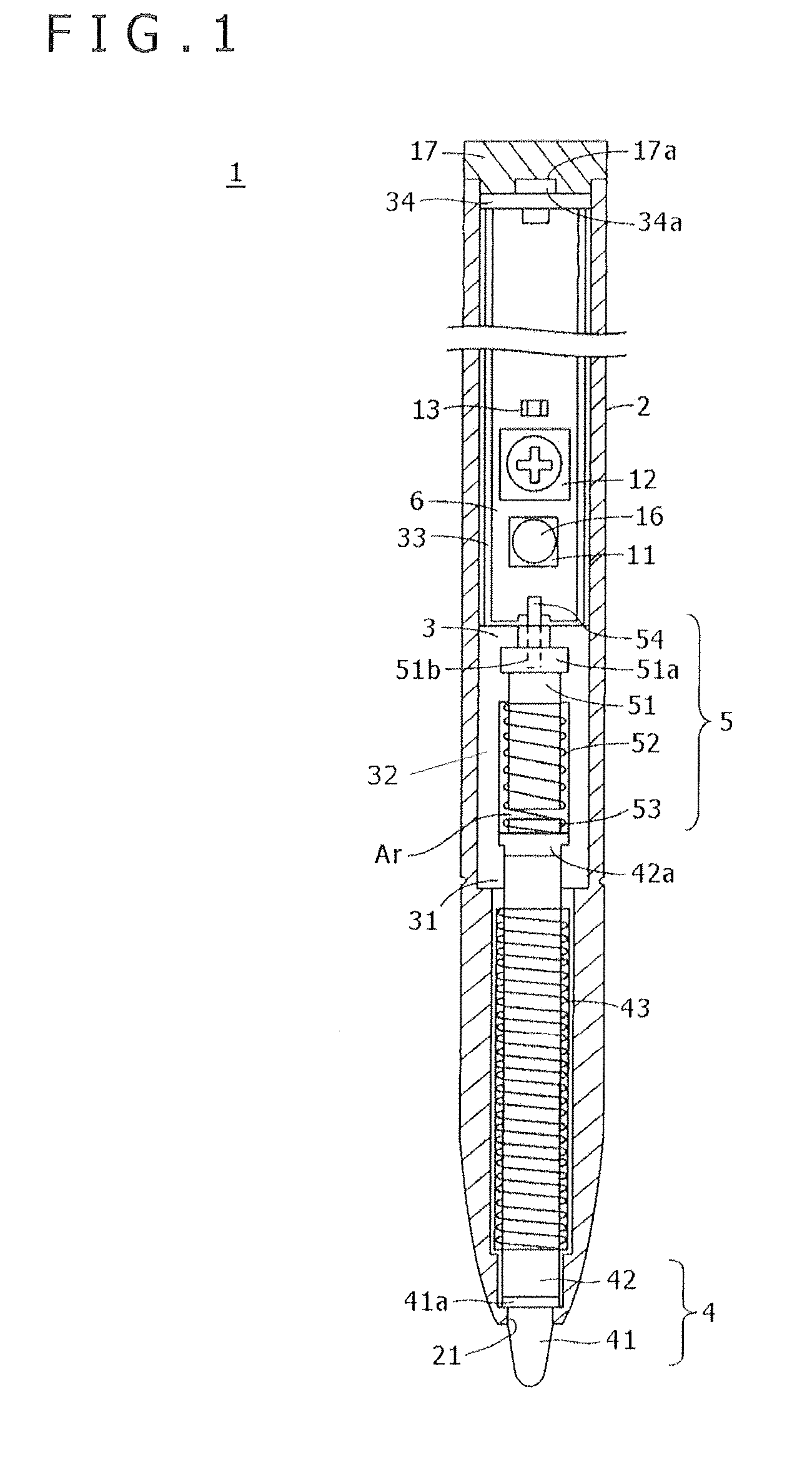
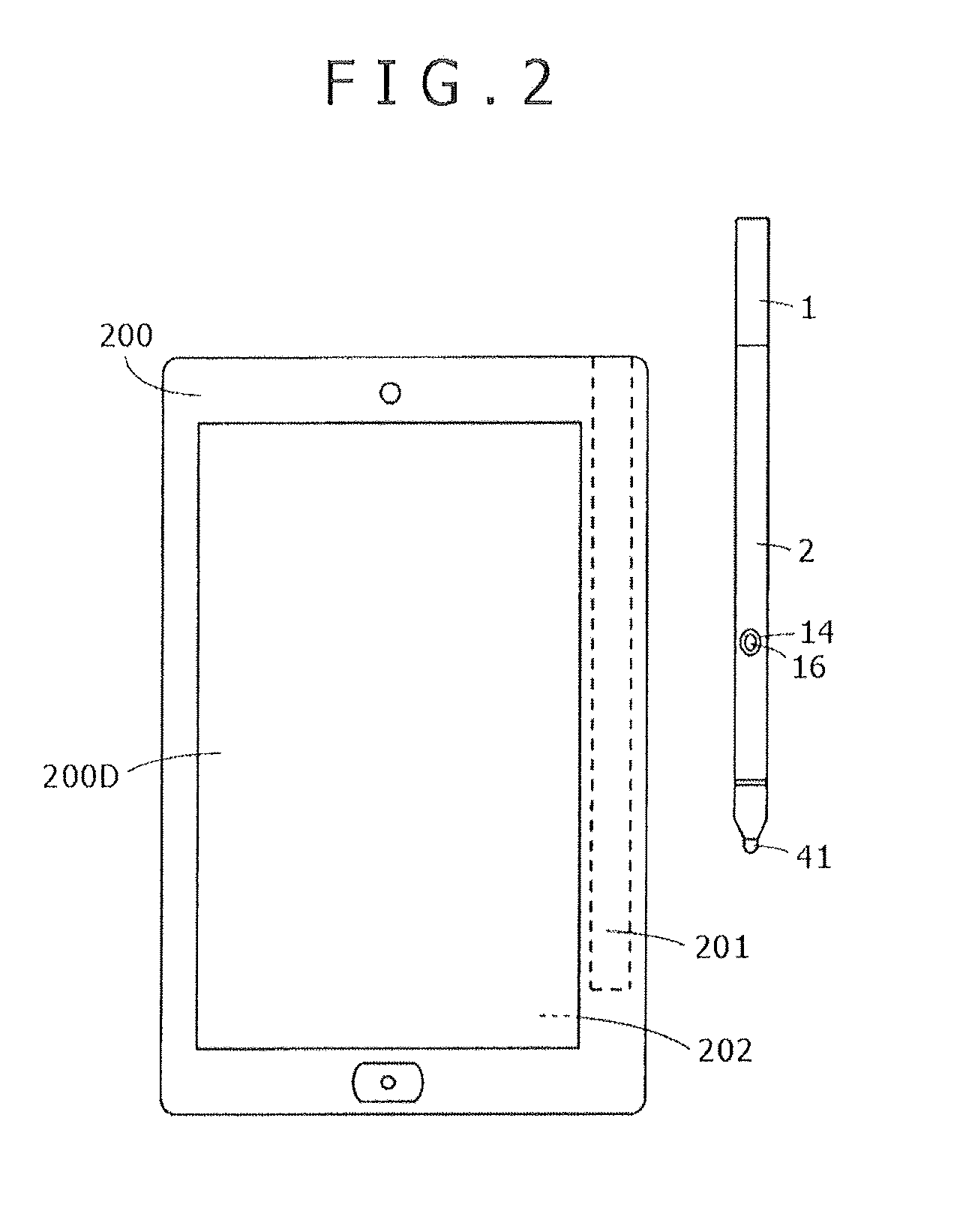
[0052]FIG. 1 illustrates a structure of a pen-shaped position indicator 1 according to a first embodiment of the present invention. In addition, FIG. 2 is a top plan view showing an example of an electronic apparatus 200 for use with the pen-shaped position indicator 1 according to the first embodiment of the present invention. In the case shown in FIG. 2, the electronic apparatus 200 is, for example, a high-performance cellular phone unit including a display screen 200D of a display device, such as a Liquid Crystal Display (LCD) device. Also, in the illustrated embodiment, the electronic apparatus 200 includes an electromagnetic induction type position detector 202 on a lower portion (back side) of the display screen 200D.

[0053]A chassis of the electronic apparatus 200 in this case is provided with an accommodation concave hole 201 for accommodating therein the pen-shaped position indicator 1. A user takes out the pen-shaped position indicator 1 accommodated in the accommodation co...

second embodiment

[0118]In the first embodiment of the present invention described above, the holder 3 has the shape which is obtained by partially cutting out the cylinder corresponding to the hollow portion of the case 2 along the axial direction, and the cut-out portion is held as the opening portion. With the case of the holder 3 having such a structure, there is no problem as long as the worker accommodates the ferrite core 42, the pressure-sensitive component 5, and the printed wiring board 6 in the holder 3, and without interruption places the holder 3 in the case 2.

[0119]However, when the work is carried out in such a way that the ferrite core 42, the pressure-sensitive component 5, and the printed wiring board 6 are assembled to be disposed and held in the holder 3, and then the resulting assembly is held to be inserted in the case 2 at a later time, the opening portions of the holder 3 cannot be dust proofed.

[0120]A second embodiment of the present invention is a modification of the first e...

third embodiment

Modifications to Third Embodiment

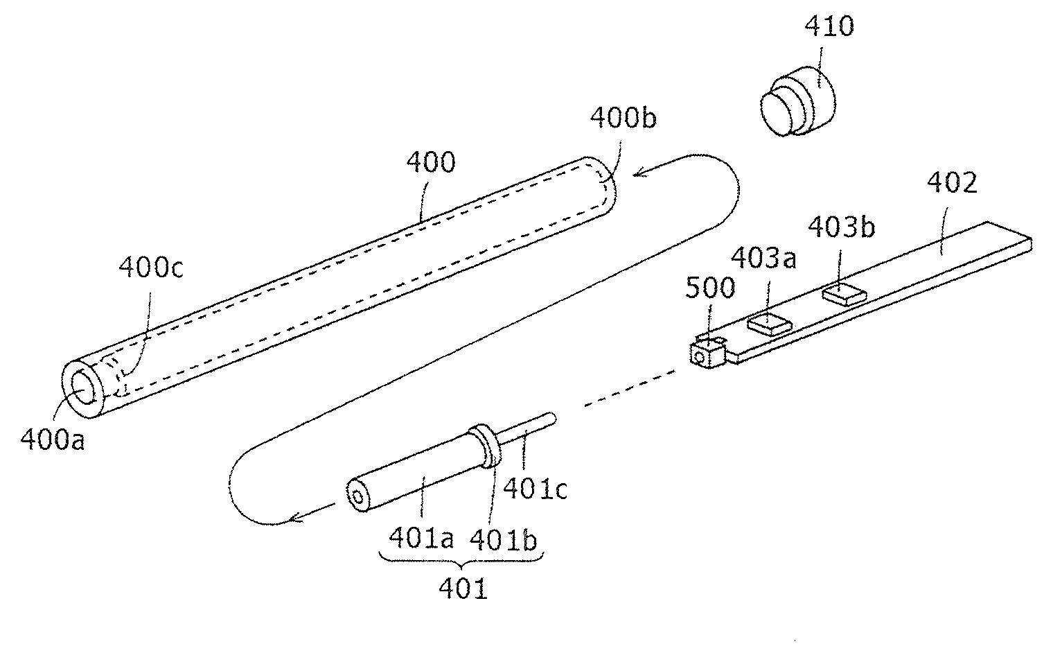
[0143]In the third embodiment described above of the present invention, the position indicating coil 301, which is wound around the small diameter portion 302a of the ferrite core 302, protrudes from the opening portion 300a of the holder 300. However, another structure may be adopted such that the position indicating coil 301 is accommodated in the holder 300 in such a way that only a protrusion member coupled to the ferrite core 302 protrudes from the opening portion 300a of the holder 300 to the outside. FIG. 10 is a view showing an arrangement of the components within the holder 300 in such a case.

[0144]That is to say, in the case shown in FIG. 10, the protrusion member 310, which is fitted into the side opposite to the guard portion 302b of the ferrite core 302, has a shape including both of a guard portion 310b and a small diameter portion 310a. A diameter of the small diameter portion 310a of the protrusion member 310 is set slightly smaller t...


PUM


Abstract

A position indicator is provided, which includes a chassis that accommodates a holder therein, wherein the holder in turn accommodates various elements therein. The holder includes a core body engaging portion configured to hold a core body, a component disposing portion in which one or more pressure-sensitive components are disposed in an axial direction so as to receive a pressing pressure applied to the core body, and a printed wiring board mounting portion for being engaged with and mounting a printed wiring board with a longitudinal direction of the printed wiring board as the axial direction. The core body and the one or more pressure-sensitive components are held by the core body engaging portion and the component disposing portion in such a way that their central positions are aligned with each other in a predetermined position.

Description

CROSS-REFERENCE TO RELATED APPLICATION(S)[0001]The present application claims priority under 35 U.S.C. 119(a) of Japanese Application No. 2012-092345, filed Apr. 13, 2012, the entire content of which is incorporated herein by reference.BACKGROUND OF THE INVENTION[0002]1. Field of the Invention[0003]The present invention relates to a position indicator, having a pen-like shape for example, which is used together with a position detector, and more particularly to a position indicator which has a function of detecting a pressure applied to a tip portion of the position indicator.[0004]2. Description of the Related Art[0005]In recent years, a position input device as an input device has been used in a tablet type personal computer (PC) or the like. The position input device is composed, for example, of a position indicator which is formed so as to have a pen-like shape, and a position detector having an input surface, on which a pointing operation is carried out, characters, figures or ...

Claims


Application Information

Patent Timeline
Patent Type & Authority Applications(United States)
IPC IPC(8): G01B5/00
CPCG01B5/0004G06F2200/1632G06F3/046G06F3/03545G06F3/033G06F1/16
Inventor FUKUSHIMA, YASUYUKIFUJITSUKA, HIROYUKI
Owner WACOM CO LTD
Why Eureka
Try Eureka