

Pipe Section Having Bonded Composite Barrier Layer
a composite barrier and pipe section technology, applied in the direction of rigid containers, synthetic resin layered products, propulsion parts, etc., can solve the problems of unreinforced barrier layers, inability to meet the requirements of many applications, and inability to provide the characteristics of many applications
- Summary
- Abstract
- Description
- Claims
- Application Information
AI Technical Summary
Benefits of technology
Problems solved by technology
Method used
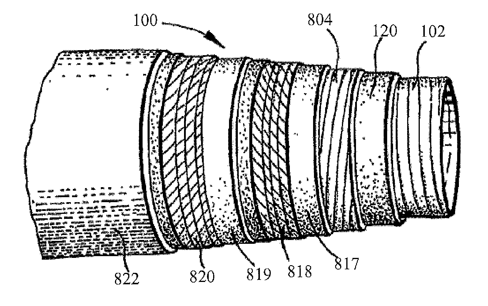
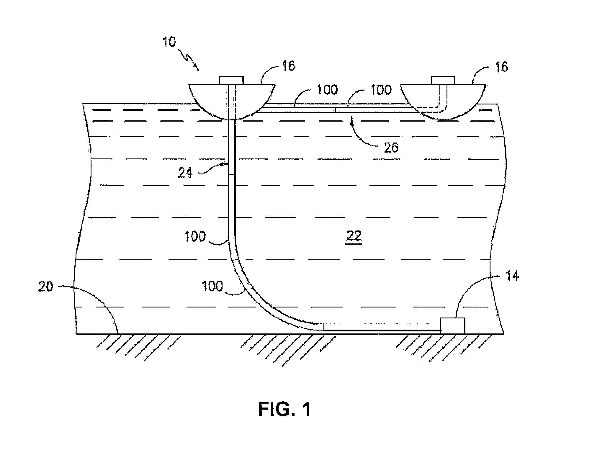
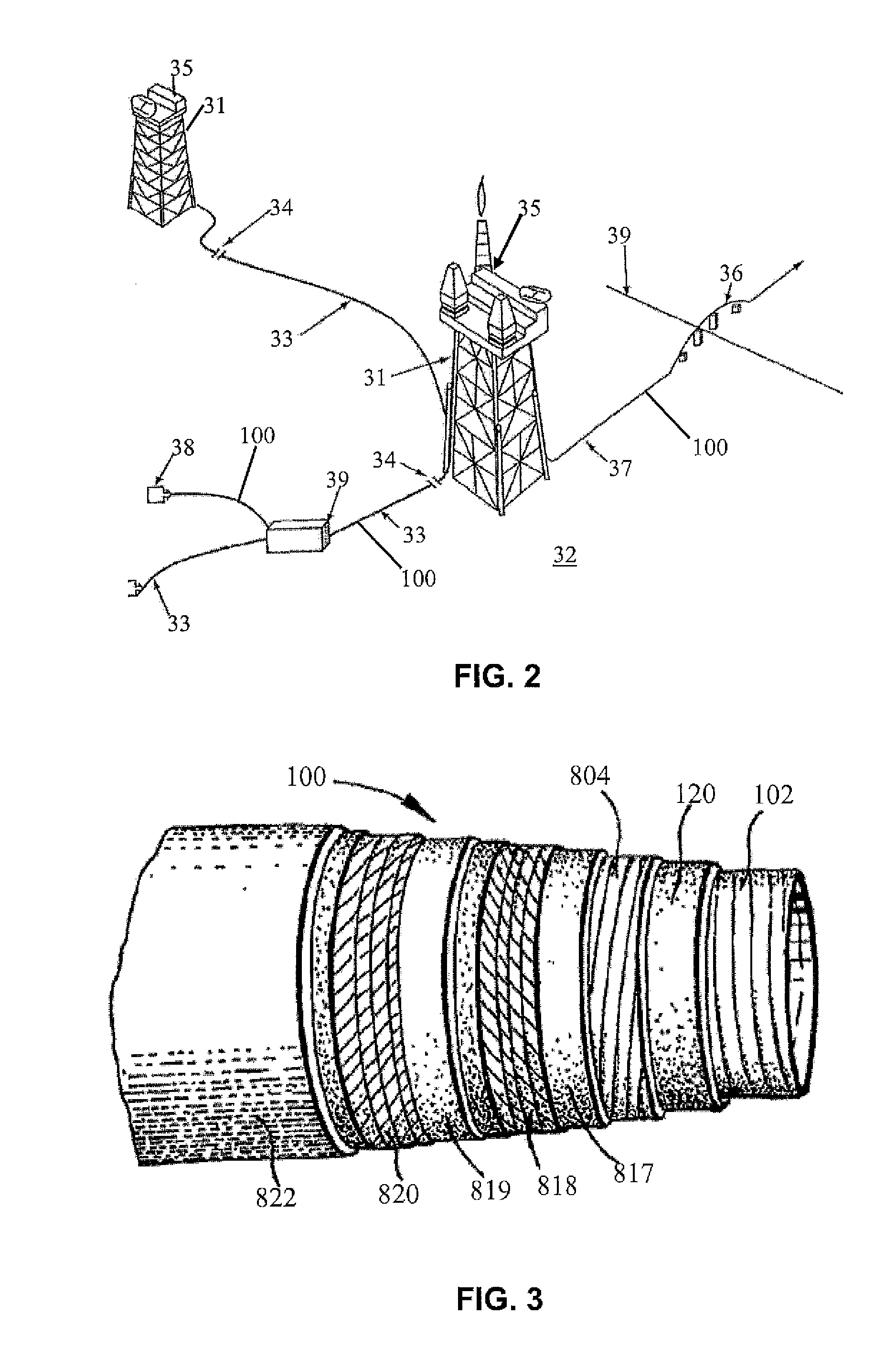
Image

Examples
example 1
[0218]Materials utilized to form the compositions included the following:
[0219]Polyarylene sulfide: Fortron® 0214 linear polyphenylene sulfide available from Ticona Engineering Polymers of Florence, Ky.
[0220]Impact Modifier: LOTADER® AX8840—a random copolymer of ethylene and glycidyl methacrylate available from Arkema, Inc.
[0221]Crosslinking Agent: Terephthalic Acid
[0222]Disulfide: 2,2-dithiodibenzoic acid
[0223]Lubricant: Glycolube® P available from Lonza Group Ltd.
[0224]Materials were melt mixed using a Coperion co-rotating, fully-intermeshing, twin-screw extruder with an overall L / D of 40 and ten temperature control zones including one at the die. A high shear screw design was used to compound the additives into a resin matrix. The polyarylene sulfide, impact modifier and lubricant were fed to the main feed throat in the first barrel by means of a gravimetric feeder. Upon melting and mixing of the above ingredients, the disulfide was fed using a gravimetric feeder at barrel 6. Mat...
example 2
[0229]Materials as described in Example 1 were melt mixed using a Coperion co-rotating, fully-intermeshing, twin-screw extruder with an overall L / D of 40 and ten temperature control zones including one at the die. A high shear screw design was used to compound the additives into a resin matrix. The polyarylene sulfide, impact modifier and lubricant were fed to the main feed throat in the first barrel by means of a gravimetric feeder. The disulfide was fed using a gravimetric feeder at various locations in the extruder; at the main feed throat, at barrel 4 and barrel 6. The crosslinking agent was fed at barrel 6. Materials were further mixed then extruded through a strand die. The strands were water-quenched in a bath to solidify and granulated in a pelletizer.
[0230]Comparative Samples 3 and 4 were formed of the same composition and compounded by use of a different screw design.
TABLE 4AdditionPoint345678910Lubricantmain feed0.30.30.30.30.30.30.30.3Crosslinkingbarrel 6——0.51.01.00.50....
example 3
[0238]Materials as described in Example 1 were melt mixed using a Coperion co-rotating, fully-intermeshing, twin-screw extruder with an overall L / D of 40 and ten temperature control zones including one at the die. A high shear screw design was used to compound the additives into a resin matrix. The polyarylene sulfide, impact modifier and lubricant were fed to the feed throat in the first barrel by means of a gravimetric feeder. The crosslinking agent was fed using a gravimetric feeder at the main feed throat and at barrel 6. Materials were further mixed then extruded through a strand die. The strands were water-quenched in a bath to solidify and granulated in a pelletizer.
[0239]Compositions of the samples are provided in Table 8, below. Amounts are provided as weight percentages based upon the weight of the sample.
TABLE 8AdditionSampleSampleSampleSampleComponentPoint11121314Lubricantmain0.30.30.30.3feedCrosslinkingmain—0.51.0—AgentfeedCrosslinkingbarrel 6———1.0AgentImpactmain15.015...
PUM
| Property | Measurement | Unit |
|---|---|---|
| depth | aaaaa | aaaaa |
| depth | aaaaa | aaaaa |
| depth | aaaaa | aaaaa |
Abstract
Description
Claims
Application Information