
Apparatus and method for generating light pulses from leds in optical absorption gas sensors

a technology of optical absorption gas and apparatus, applied in the direction of material analysis through optical means, instruments, transmissivity measurements, etc., can solve the problems of high signal-to-noise ratio, complex control electronics, and output from leds sensitive to temperature, so as to reduce quantisation effects

Active Publication Date: 2013-10-17
GAS SENSING SOLUTIONS
View PDF17 Cites 21 Cited by
  • Summary
  • Abstract
  • Description
  • Claims
  • Application Information

AI Technical Summary

Benefits of technology

The patent text describes a method for measuring the shape of a light pulse using an LED, which can be used to determine various features of the pulse. This information can be used to compensate for changes in the LED or the photosensor, and to regulate the output of the photosensor to prevent it from exceeding the dynamic range of the analog-to-digital converter. The method allows for simpler and more cost-effective circuitry and reduces power consumption.

Problems solved by technology

Secondly, a pulsed source of light consumes less energy than a source which emits light continuously at the same peak power consumption.
Furthermore, LEDs have maximum operating currents above which the LED would be damaged by the resulting heat were the LED operated continuously and pulsing allows higher maximum operating currents and therefore higher peak outputs of light than would otherwise be the case.
One complication is that the output from an LED is sensitive to temperature (amongst other factors).
This presents a technical problem, as it is necessary to control or compensate in some way for this variation with temperature.
However, known circuits to drive LEDs to provide short pulses of light, with a high signal-to-noise ratio and clear pulse shaping, require complex control electronics and consume a substantial amount of power.

Method used


Image

  • Apparatus and method for generating light pulses from leds in optical absorption gas sensors
  • Apparatus and method for generating light pulses from leds in optical absorption gas sensors
  • Apparatus and method for generating light pulses from leds in optical absorption gas sensors

Examples


Embodiment Construction

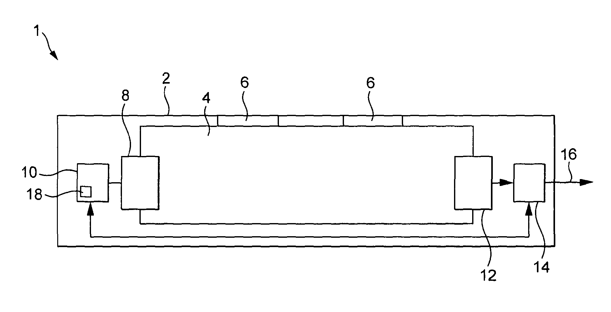
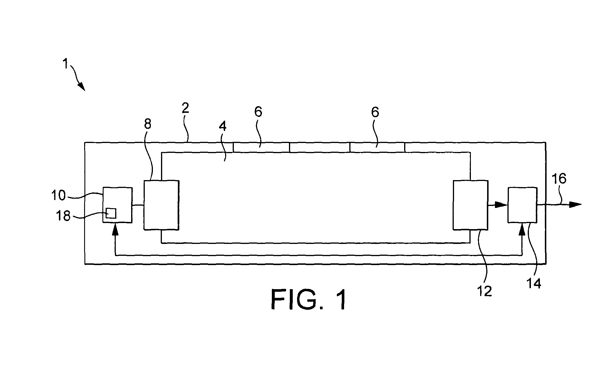
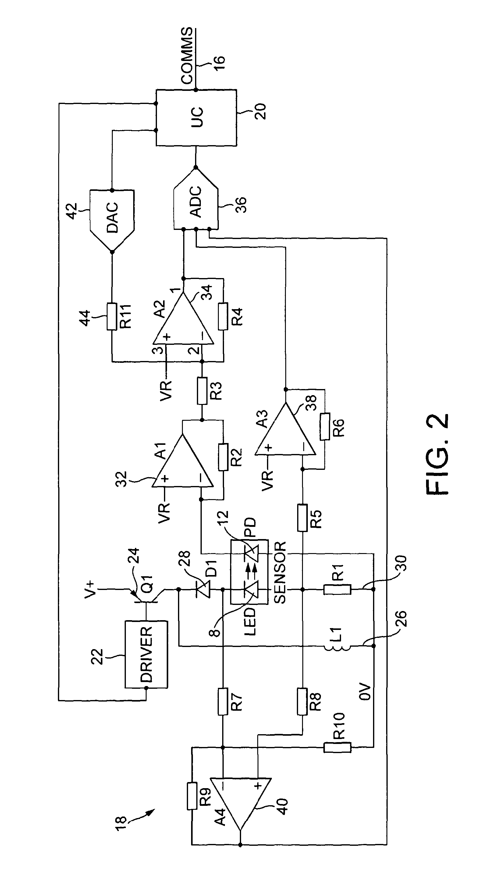
[0047]With reference to FIG. 1, an optical absorption gas sensor 1 has a body 2 defining a gas sample chamber 4, into which a gas sample can pass by diffusion through one or more apertures 6. A light emitting diode 8 functions as a light source, and is driven by an LED control and pulse measurement circuit 10. A photodiode 12 functions as a photosensor, and has an output current dependent on the light which falls on the photodiode junction. The current from the photodiode is amplified and processed by a control and compensation circuit 14 including a microcontroller, which implements a compensation function and thereby provides a compensated signal through an output 16. The control and compensation circuit also receives information concerning the shape of LED pulses and controls the LED control circuit.

[0048]The gas sample chamber may have any of a large number of configurations known to those skilled in the art, and typically includes a reflective inner surface, so that light from ...


PUM

PropertyMeasurementUnit
inductanceaaaaaaaaaa
currentaaaaaaaaaa
voltageaaaaaaaaaa

Abstract

An optical absorption gas sensor for detecting an analyte gas comprises a gas sample receiving chamber, at least one light emitting diode (LED) and a photodiode or other photosensor. A plurality of light pulses are generated by passing pulses of current through the at least one LED. The current through the at least one LED is measured a plurality of times during each pulse and taken into account when generating a compensated output signal. The transfer ratio between LED current and photodiode output signal is calculated a plurality of times during each pulse. An ADC measures the LED and photodiode currents alternately. The LED pulses are generated by inductor discharge flyback and the period of time for which current is supplied to the inductor prior to each pulse is selected so that the photodiode output current is at an optimal region within the input range of the ADC. At least the temperature of the at least one LED is measured and taken into account when generating the compensated output signal. Thus, rather than providing especially careful control of the LED pulses, the pulses are measured, enabling a simpler, lower power circuit which is tolerant of variations in temperature to be provided.

Description

FIELD OF THE INVENTION[0001]1. Background to the Invention[0002]The invention relates to the field of optical absorption gas sensors which employ an LED (for example, an infra-red LED) as a source of light.[0003]2. Background to the Invention[0004]Optical absorption gas sensors include both a source of light and a detector of light (a photosensor). Light from the source is directed through a gas sample and detected by the photosensor. The concentration of an analyte gas in the gas sample can be determined from the absorption of light by the analyte gas. Typically, either the source will emit light predominantly within a wavelength range corresponding to absorption lines of the intended analyte, or the photosensor will be sensitive to light predominantly within a wavelength range corresponding to absorption lines of the intended analyte, either due to the inherent properties of the light sensitive transducer which is employed (e.g. a photodiode) or due to the presence of a wavelength...

Claims


Application Information

Patent Timeline
Patent Type & Authority Applications(United States)
IPC IPC(8): G01N21/61
CPCG01N21/61G01N21/274G01N21/3504G01N2201/0696G01N2201/1211G01N2201/127G01J11/00
Inventor MACGEGOR, CALUM JOHNGIBSON, DESMOND ROBERT
Owner GAS SENSING SOLUTIONS
Learn More