Radio communication system, base station, and interference management scheme
a radio communication system and interference management technology, applied in the field of interference control techniques, can solve problems such as degrading the communication quality of the lpn user, and achieve the effect of minimizing the reduction of the throughput of the macro base station and improving the lpn
- Summary
- Abstract
- Description
- Claims
- Application Information
AI Technical Summary
Benefits of technology
Problems solved by technology
Method used
Image
Examples
first embodiment
[0070]A first embodiment to address the problems will be described with reference to FIGS. 6 to 17.
[0071]Operation Procedure
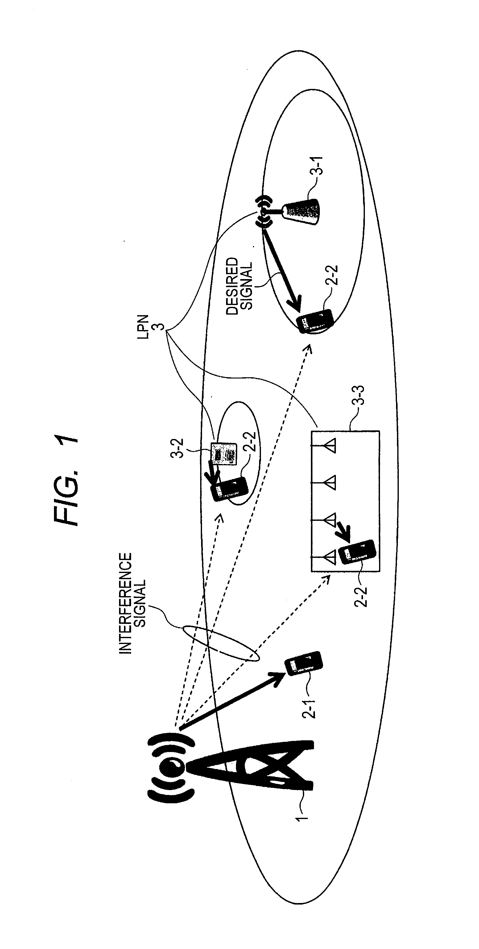
[0072]FIG. 6 is an exemplary operation procedure according to the first embodiment. In the embodiment, numerals 10 and 30 are considered to be a macro base station and an LPN, respectively.
[0073]The procedures from Steps S1 to S6 in FIG. 6 are the same as the procedures in FIG. 3. Points different from the operations of the LPN 30 are the operations in Steps S11 and S12 in FIG. 3.
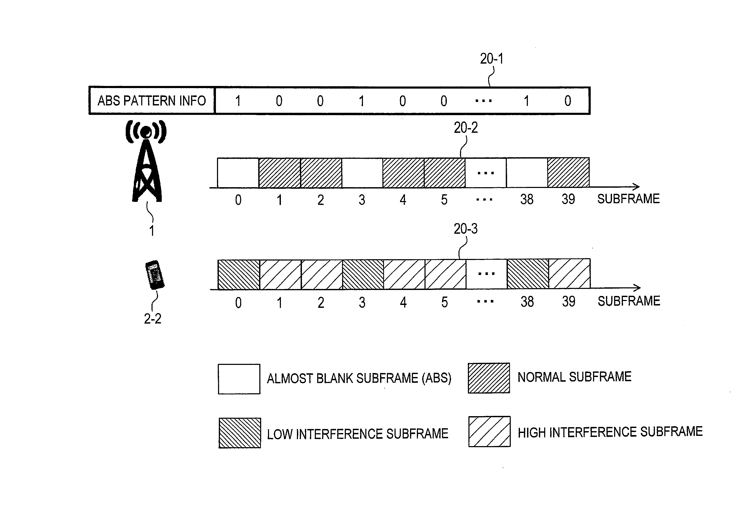
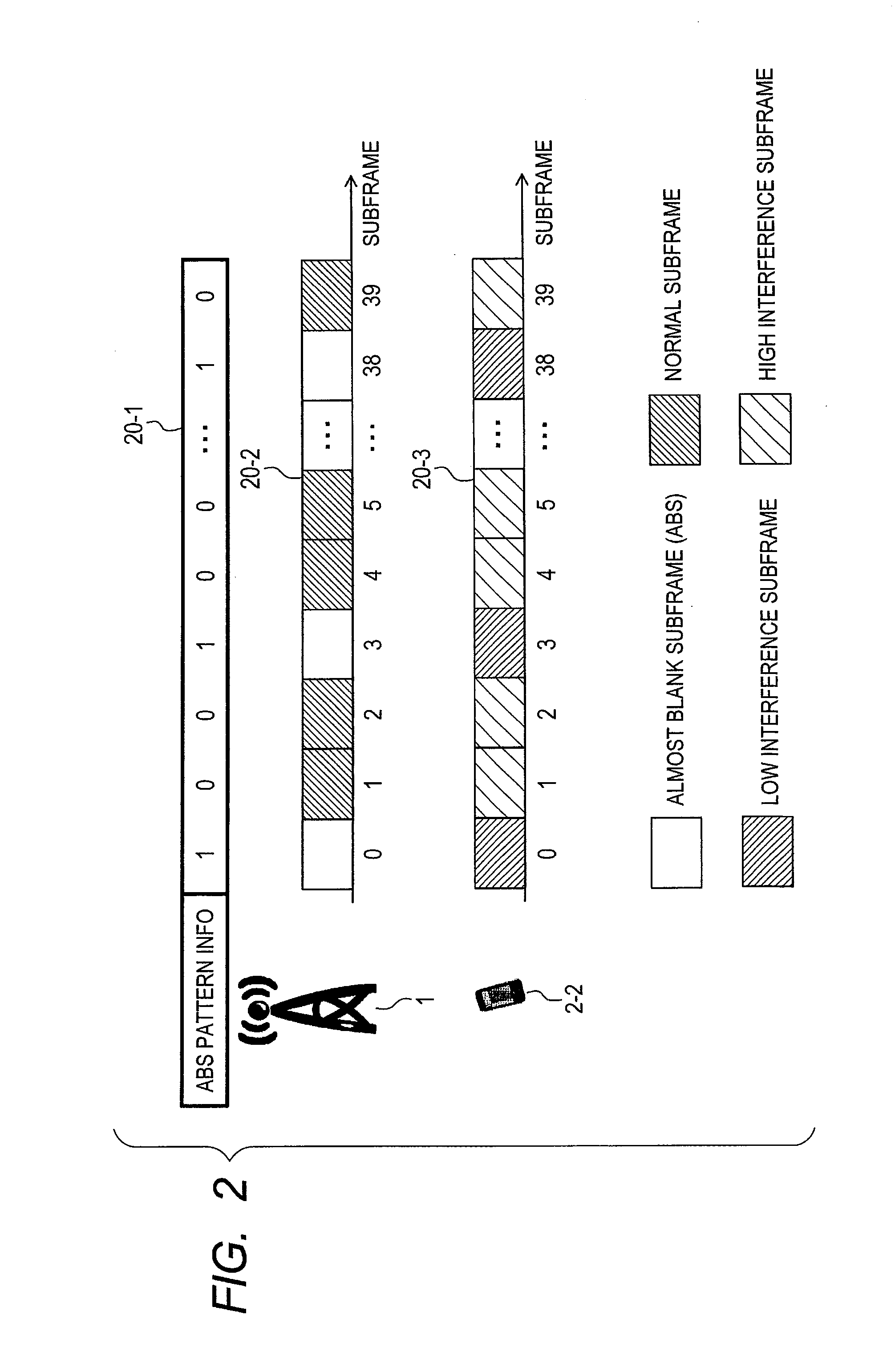
[0074]In Step S11, the processing unit of the LPN 30 uses the ABS CQI and the normal subframe CQI of the LPN users 2-2 acquired at Step S4 to calculate the relationship between the ABS ratio of the macro base station 10 and the throughput prediction values of the LPN users 2-2. In Step S12, the processing unit reports the calculated throughput prediction values of the LPN users 2-2 to the macro base station 10.
[0075]FIG. 7 is exemplary throughput prediction values reported from the LPN...
second embodiment
[0124]In a second embodiment, the macro base station 1 also calculates the throughput prediction values of the LPN users 2-2. For example, the second embodiment is effective in the case of a centralized base station configuration as in FIG. 18, in which an LPN 30 and a macro base station 10 are connected to each other through cables such as an optical fiber. In this case, the LPN 30 is in a RRH configuration only including the antenna 41 and the RF unit 42 in FIG. 11 and a photoelectric converter. The components after the baseband signal processing unit 43 may be put together at the same location as the macro base station 10.
[0125]FIG. 19 is an exemplary operation procedure according to the second embodiment. The operations in Steps S1 to S6 in FIG. 19 may be the same as in FIG. 6. In Step S31, the LPN 30 reports the ABS CQI and the normal subframe CQI of LPN users 2-2 acquired in Step S4 to the macro base station 10. FIG. 20 is examples of the ABS CQI and the normal subframe CQI of...
third embodiment
[0127]In a third embodiment, an ABS controller 101 different from a macro base station 10 and an LPN 30 determines the ABS ratio and the ABS pattern. FIG. 21 is an exemplary system configuration according to the third embodiment. The macro base station 10 and the LPN 30 are connected to the ABS controller 101 through a network I / F 102, or directly connected thereto. A plurality of the macro base stations 10 and a plurality of the LPNs 30 may be connected to the ABS controller 101.
[0128]FIG. 22 is an exemplary operation procedure in the case where the ABS controller 101 exists. First, the ABS controller 101 decides the ABS pattern (S41), and informs the ABS pattern to the macro base station 10 and the LPN 30 (S42). The macro base station 10 and the LPN 30 receive information about the ABS pattern, and configure the macro user 2-1 and the LPN user 2-2 to report the CQI measured in the ABS and the normal subframe (S43). In the case where the macro base station 10 stops transmission, or...
PUM
 Abstract
Description
Claims
Application Information
 - R&D
- Intellectual Property
- Life Sciences
- Materials
- Tech Scout
- Unparalleled Data Quality
- Higher Quality Content
- 60% Fewer Hallucinations
Browse by: Latest US Patents, China's latest patents, Technical Efficacy Thesaurus, Application Domain, Technology Topic, Popular Technical Reports.
© 2025 PatSnap. All rights reserved.Legal|Privacy policy|Modern Slavery Act Transparency Statement|Sitemap|About US| Contact US: help@patsnap.com


