
Passive containment air cooling for nuclear power plants

a technology of containment air and nuclear power plant, which is applied in nuclear engineering, nuclear elements, greenhouse gas reduction, etc., can solve the problems of reducing the driving force for the leakage of fission products from the containment to the atmosphere, and significant increase in containment pressure and temperatur

Inactive Publication Date: 2013-10-17
WESTINGHOUSE ELECTRIC CORP
View PDF9 Cites 28 Cited by
  • Summary
  • Abstract
  • Description
  • Claims
  • Application Information

AI Technical Summary

Benefits of technology

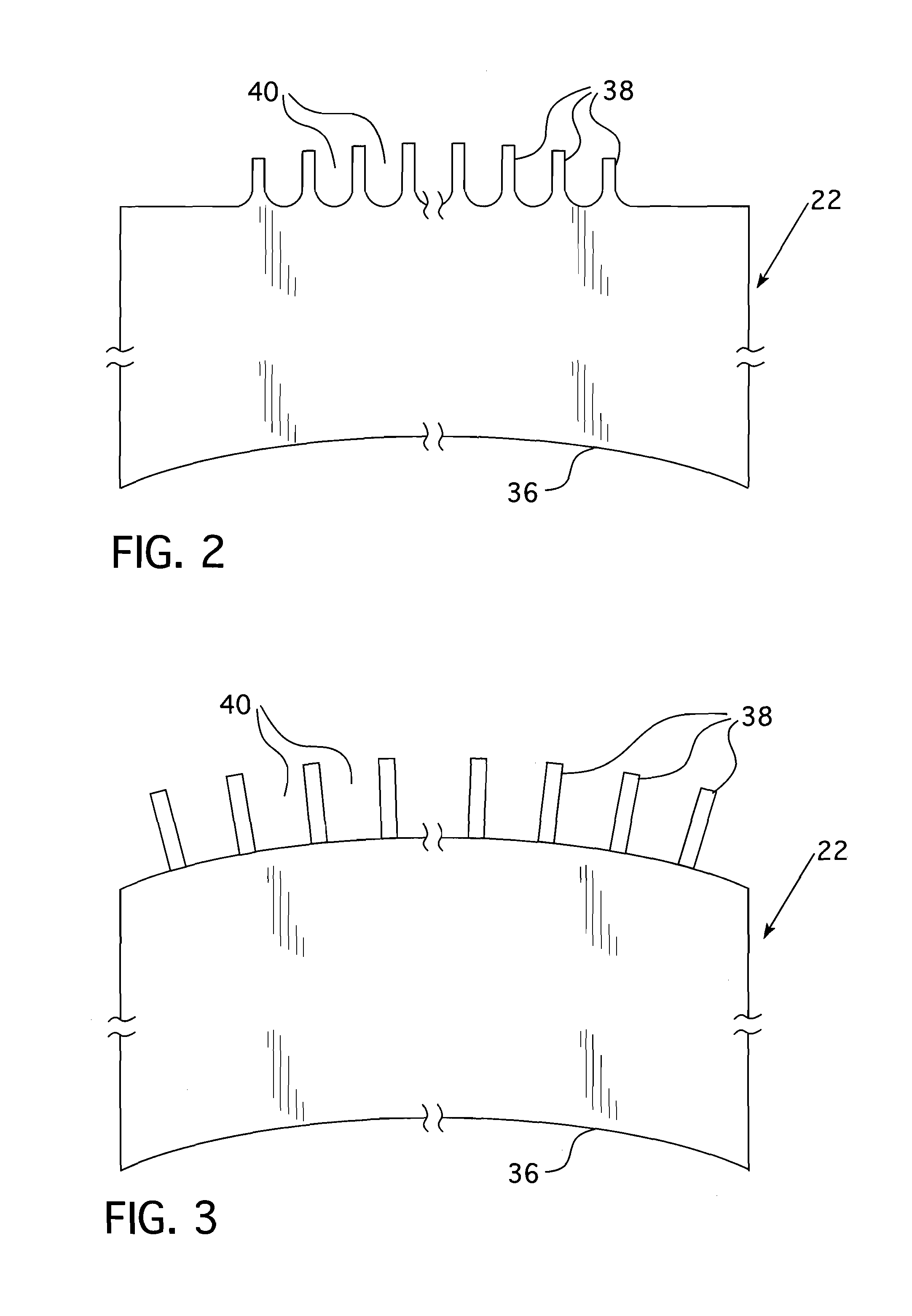
The invention is a solid metal shell that surrounds a nuclear reactor plant to enhance its safety. The shell has a tortuous path on its exterior surface where a cooling fluid can flow and follow the path. The interior surface of the shell is smooth. The tortuous path is made up of indentations and protrusions on the exterior surface. The indentations and protrusions are arranged in a pattern and attached to the shell through a heat conducting path. The pattern can be a series of modules, each with a pattern of indentations and protrusions. The tortuous path can be formed by a pattern of fins or trips on the exterior surface of the shell. The invention improves the heat transfer between the cooling fluid and the shell, ensuring better safety and efficiency of the reactor plant.

Problems solved by technology

The passive containment cooling system also serves as a means of transferring heat for other events resulting in a significant increase in containment pressure and temperature.
The passive containment cooling system also limits releases of radioactivity (post accident) by reducing the pressure differential between the containment atmosphere and the external environment, thereby diminishing the driving force for leakage of fission products from the containment to the atmosphere.

Method used


Image

  • Passive containment air cooling for nuclear power plants
  • Passive containment air cooling for nuclear power plants
  • Passive containment air cooling for nuclear power plants

Examples


Embodiment Construction

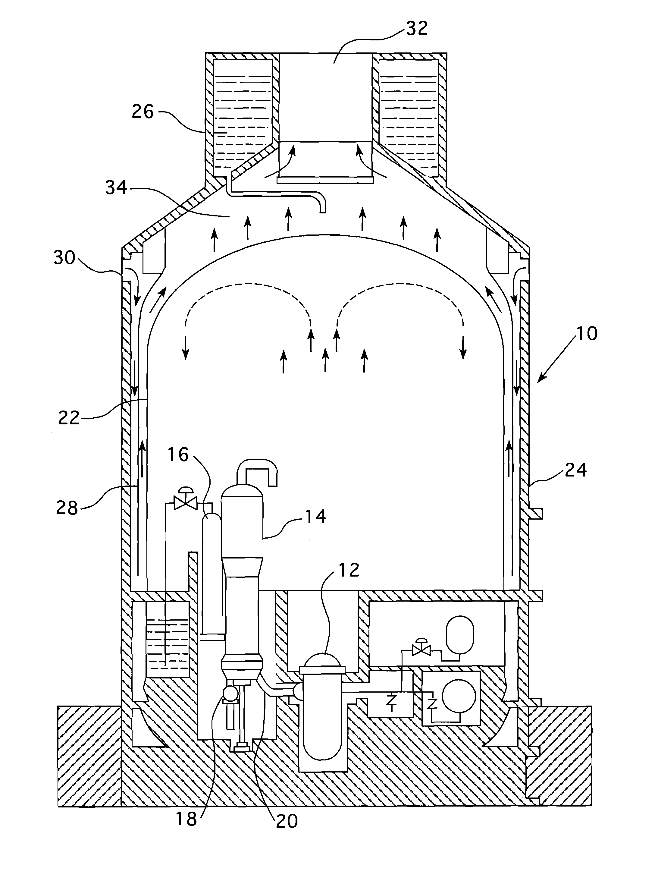
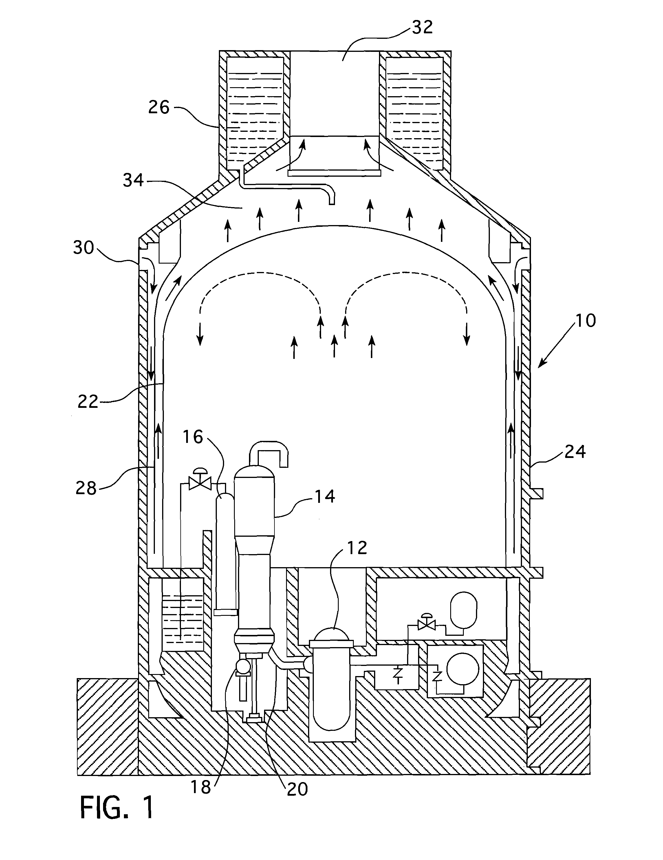
[0027]As previously mentioned, in an AP1000 passive cooling containment system, the convective heat transfer to the air by the heated containment steel surface only accounts for a small portion of the total heat transfer; such total heat transfer being primarily accomplished by the evaporation of water from the wetted areas of the containment steel surface, which cools the water on the surface, which then cools the containment steel, which then cools the inside containment atmosphere and condenses steam. This invention enables air cooling alone to provide sufficient heat removal to maintain acceptably low containment pressure with no reliance on active components, operator actions, or auxiliary water supplies, after the initial three days when the initial water volume in the passive containment cooling water storage tank 26 has been exhausted.

[0028]The foregoing object is achieved by creating a tortuous air path in or on at least a substantial part of the exterior surface of the ste...


PUM


Abstract

An enhanced passive containment air cooling system for a nuclear power plant that increases the heat transfer surface on the exterior of the nuclear plant's containment vessel. The increased surface area is created by forming a tortuous path in or on at least a substantial part of the exterior surface of the containment vessel over which a cooling fluid can flow and follow the tortuous path. The tortuous path is formed from a series of indentations and protrusions in or on the exterior surface that form a circuitous path for the cooling fluid.

Description

CROSS REFERENCE TO RELATED APPLICATIONS[0001]This application is related to co-pending patent application Ser. No. ______, (Attorney Docket NPP 2011-006), filed concurrently herewith.BACKGROUND[0002]1. Field[0003]The present invention relates to a passive containment cooling system for a nuclear reactor power plant and more specifically to a passive containment air cooling system that relies on the natural flow of air over the surface of a metal containment.[0004]2. Related Art[0005]Nuclear power has played an important part in the generation of electricity since the 1950's and has advantages over thermal electric and hydroelectric power plants due to its efficiency, safety and environmental preservation. The generation of electricity by nuclear power is accomplished by the nuclear fission of radioactive materials. Due to the volatility of the nuclear reaction, nuclear power plants are required by practice to be designed in such a manner that the health and safety of the public is a...

Claims


Application Information

Patent Timeline
Patent Type & Authority Applications(United States)
IPC IPC(8): G21C9/00
CPCG21C13/022G21D3/04Y02E30/30G21C11/083G21C15/12G21C15/18Y02E30/00
Inventor CONWAY, LAWRENCE E.OFSTUN, RICHARD P.HARKNESS, ALEX W.SCHULZ, TERRY L.
Owner WESTINGHOUSE ELECTRIC CORP
Learn More