
Island mode for nuclear power plant

a technology for nuclear power plants and islands, applied in nuclear engineering, nuclear elements, greenhouse gas reduction, etc., can solve the problems of sudden interruption loss of interconnection, and blackout of electrical power supply, so as to reduce the thermal power output of the pwr

Active Publication Date: 2013-10-17
BWXT MPOWER INC
View PDF8 Cites 21 Cited by
  • Summary
  • Abstract
  • Description
  • Claims
  • Application Information

AI Technical Summary

Benefits of technology

The patent is about a method of operating a nuclear power plant that includes a pressurized water reactor (PWR), steam generator, turbine, electric generator, and condenser. The method involves heating water in the PWR to create steam, which is then used to power the turbine and generate electricity. The generated electricity is then sent to an electrical switchyard. The patent describes a "station blackout" scenario where the nuclear power plant needs to quickly transition to an island mode. This involves disconnecting the electric generator from the switchyard, opening a bypass valve to redirect steam flow, and reducing the thermal power output of the PWR. The technical effect of this patent is to provide a reliable and safe method for operating a nuclear power plant during a station blackout scenario.

Problems solved by technology

These interconnections can be lost due to various failures.
In particular, a “blackout” occurs when power supplied to the electrical power grid is abruptly interrupted.
This approach ensures safety, but subsequently requires a lengthy reactor restart process.
Typically, power generation capacity is lost for days or longer.
Moreover, the abrupt shutdown can stress the turbine and other components.
), but venting to atmosphere raises other regulatory issues or overpressure alarms that would likely delay the operational restart of the PWR-based nuclear power plant with the power grid.

Method used


Image

  • Island mode for nuclear power plant
  • Island mode for nuclear power plant
  • Island mode for nuclear power plant

Examples


Embodiment Construction

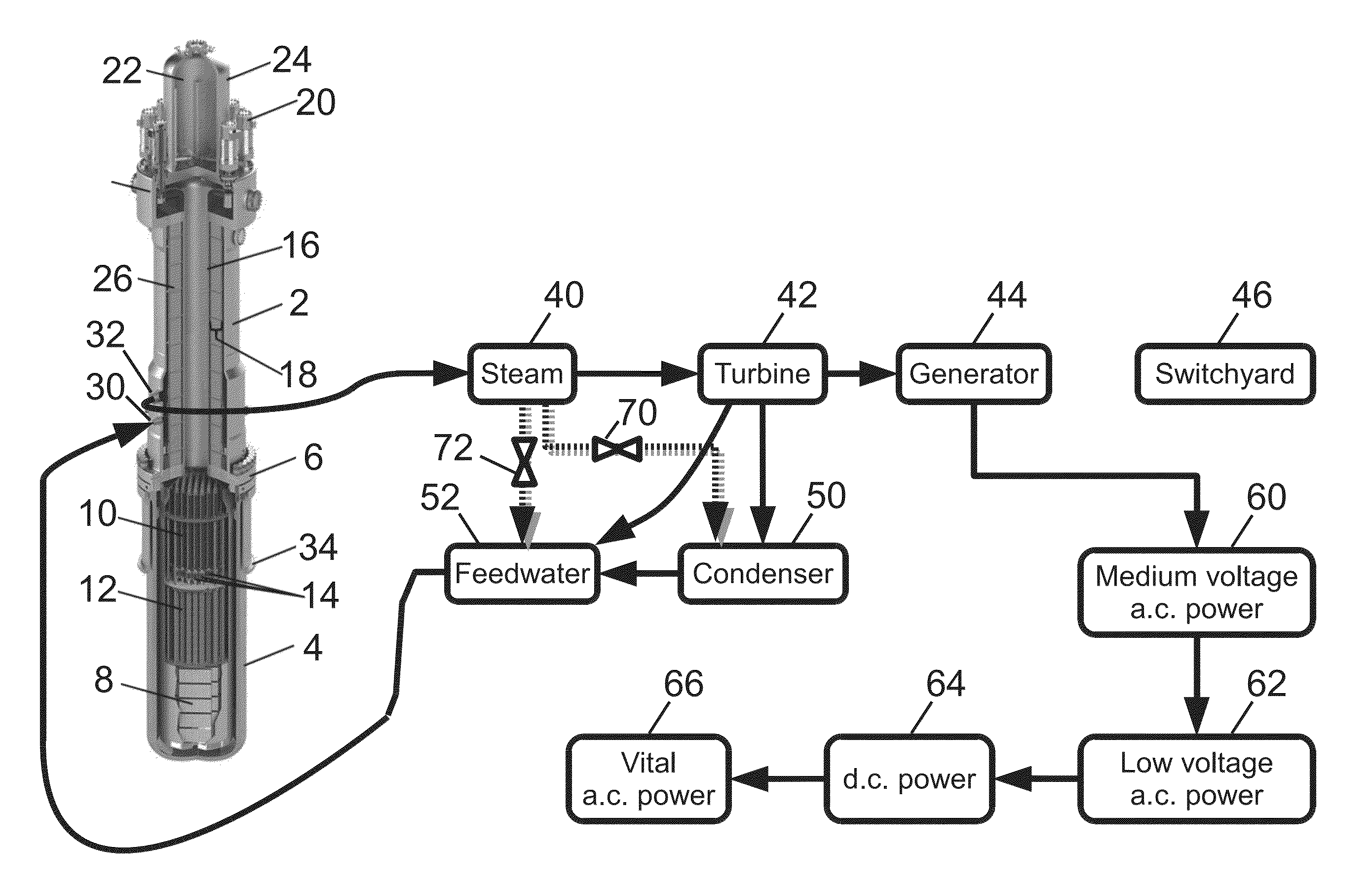
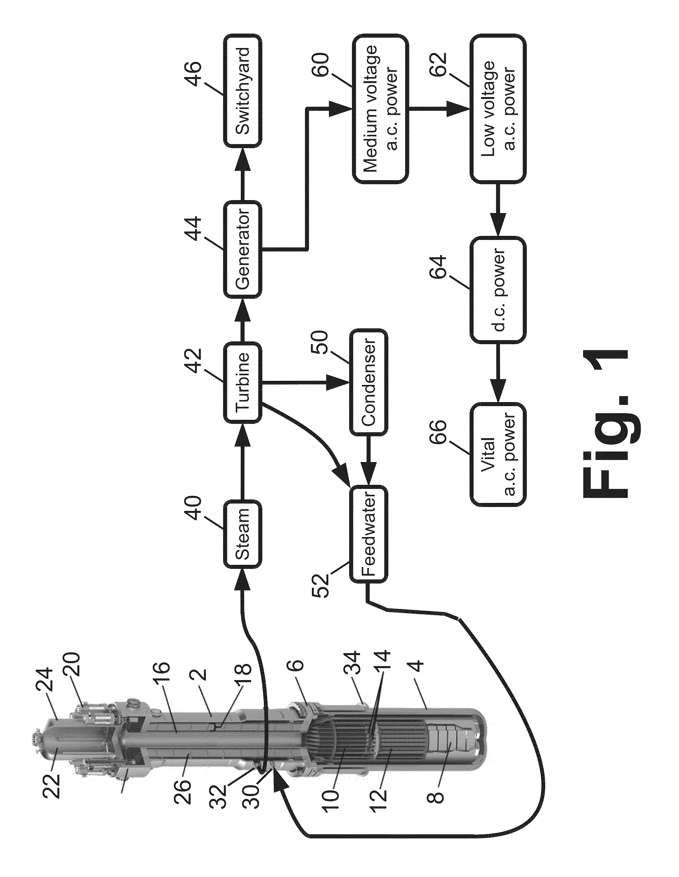
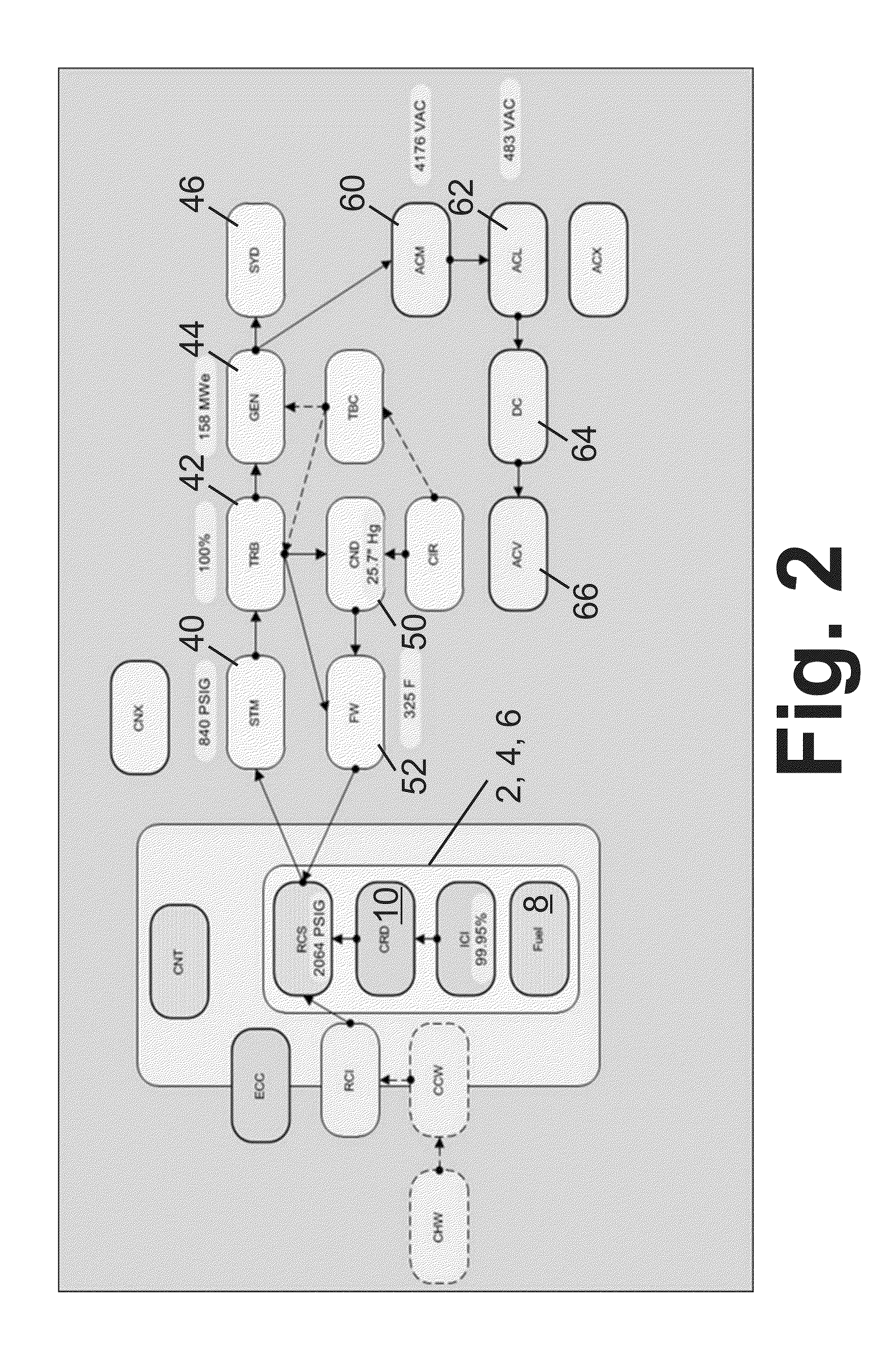
[0019]Disclosed herein are island mode operation techniques suitable for use in a pressurized water reactor (PWR). The disclosed approaches avoid venting secondary coolant steam to atmosphere, instead employing steam bypass to the condenser. Overloading of the available PWR condenser capacity is avoided by gradually closing the bypass valve over the course of the transition to island mode in order to limit the time-integrated bypass stream flow to an amount sufficient to avoid tripping steam generator or pressurizer safety valve setpoints. Additionally, in some embodiments a portion of the bypass steam flow is sent to the feedwater system rather than to the condenser, effect using the feedwater as a supplemental condenser. These aspects also reduce the stress of the transient on the turbine. In some embodiments the final reduced reactor power level is 20% or less of full capacity—at this low reactor power level, the steam bypass flow can be stopped entirely, and the plant can run in...


PUM


Abstract

A nuclear power plant comprises a pressurized water reactor (PWR) and a steam generator driving a turbine driving an electric generator. A condenser condenses steam after flowing through the turbine. Responsive to a station blackout, the nuclear power plant is electrically isolated and a bypass valve is opened to convey bypass steam flow from the steam generator to the condenser without flowing through the turbine. The thermal power output of the PWR is gradually reduced over the transition time interval. After opening, the bypass valve is gradually closed over the transition time interval. A supplemental bypass valve may also be opened responsive to the station blackout to convey supplemental bypass steam flow from the steam generator to a feedwater system supplying secondary coolant feedwater to the steam generator. The supplemental bypass steam flow does not flow through the turbine and does not flow through the condenser.

Description

[0001]This application claims the benefit of U.S. Provisional Application No. 61 / 625,325, filed Apr. 17, 2012. U.S. Provisional Application No. 61 / 625,325, filed Apr. 17, 2012, is hereby incorporated by reference in its entirety into the specification of this application.BACKGROUND[0002]The following relates to the nuclear reactor arts, nuclear power generation arts, nuclear reactor safety arts, and related arts.[0003]Electrical power grids comprise an interconnected network (i.e., “grid”) of power generation components, power transmission components, power conditioning components, and power consuming components (i.e., “loads”). Ordinarily, operation of the components is interdependent so that, for example, a power generation plant is designed to operate supplying power to a switchyard delivering power to a (cumulative) load that has known characteristics with statistically predicable narrow fluctuations.[0004]These interconnections can be lost due to various failures. In particular...

Claims


Application Information

Patent Timeline
IPC IPC(8): G21C9/00
CPCG21C9/00G21D1/02G21D3/04Y02E30/00Y02E30/30
Inventor GRAHAM, THOMAS G.
Owner BWXT MPOWER INC
Learn More