Nuclear reactor coolant pump and nuclear power plant having same

a technology of nuclear power plant and coolant pump, which is applied in the direction of nuclear reactors, nuclear elements, greenhouse gas reduction, etc., can solve the problems of increased costs and large energy loss (about 60%) while electricity is generated, and achieve the effect of reducing energy loss, reducing electricity generation, and reducing costs

Active Publication Date: 2016-09-08
KOREA ATOMIC ENERGY RES INST
View PDF3 Cites 21 Cited by
  • Summary
  • Abstract
  • Description
  • Claims
  • Application Information

AI Technical Summary

Benefits of technology

[0023]The present invention may have the following advantages.
[0024]Firstly, owing to the small driving turbine installed to generate force using steam generated from the steam generator, the reactor coolant pump can be driven by a driving force generated from the driving turbine, without an electric motor. And energy loss occurring while electricity is generated can be reduced.
[0025]Especially, in a case where the reactor coolant pump is applied to an integral reactor, the reactor coolant pump can be installed in the reactor coolant system (the reactor vessel). As a result, the reactor coolant pump can be easily applied even to a high temperature and a high pressure as a motor is removed, and the reactor coolant pump can have a compact and simplified structure. Further, since a sealing facility for preventing current leakage

Problems solved by technology

However, since the conventional reactor coolant pump uses an electric motor, and electric power for driving the electric motor is required.
In this case, a large energy loss

Method used


Image

  • Nuclear reactor coolant pump and nuclear power plant having same
  • Nuclear reactor coolant pump and nuclear power plant having same
  • Nuclear reactor coolant pump and nuclear power plant having same

Examples


Embodiment Construction

[0038]Reference will now be made in detail to the preferred embodiments of the present invention, examples of which are illustrated in the accompanying drawings. It will also be apparent to those skilled in the art that various modifications and variations can be made in the present invention without departing from the spirit or scope of the invention. Thus, it is intended that the present invention cover modifications and variations of this invention provided they come within the scope of the appended claims and their equivalents.

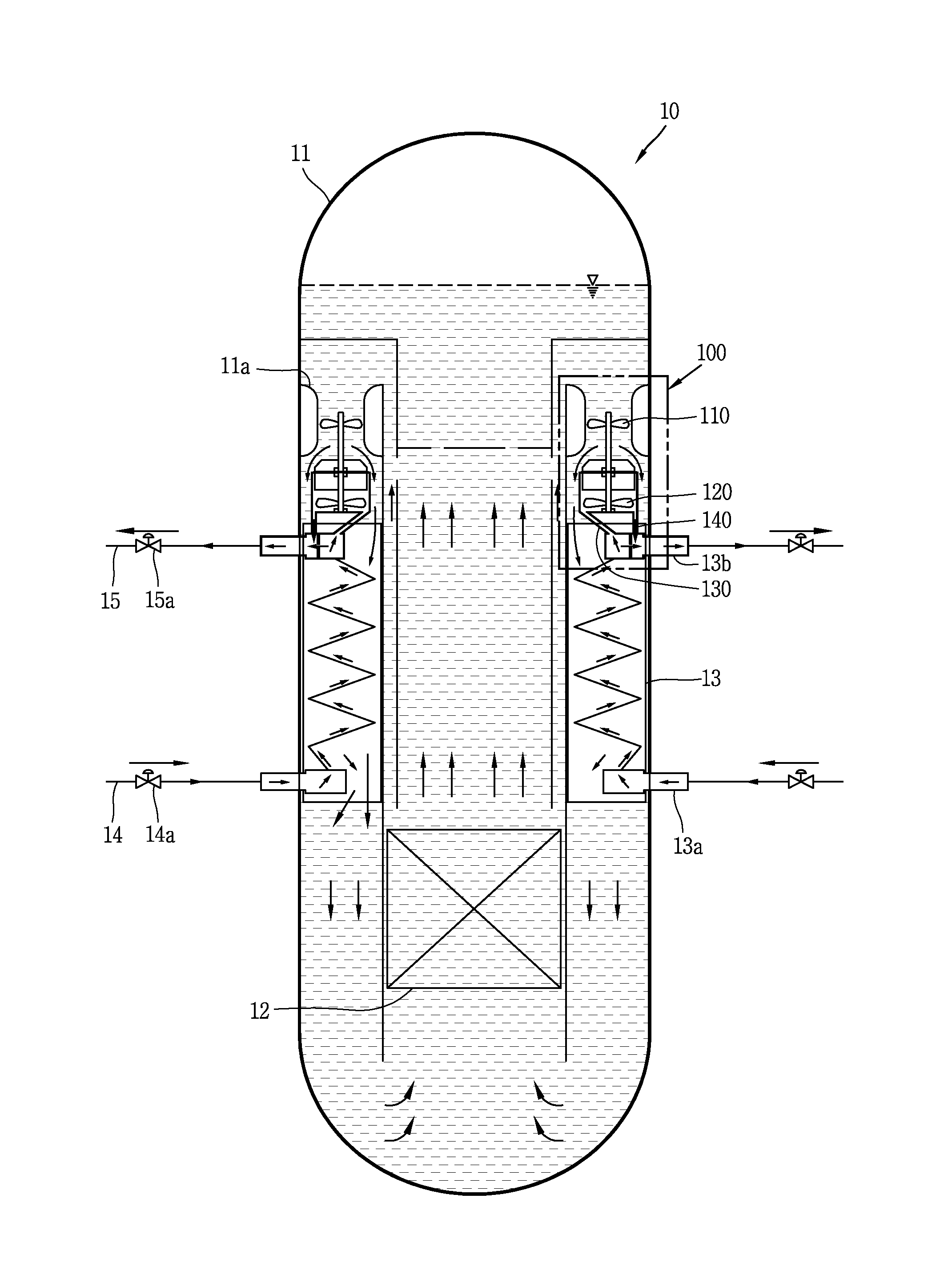
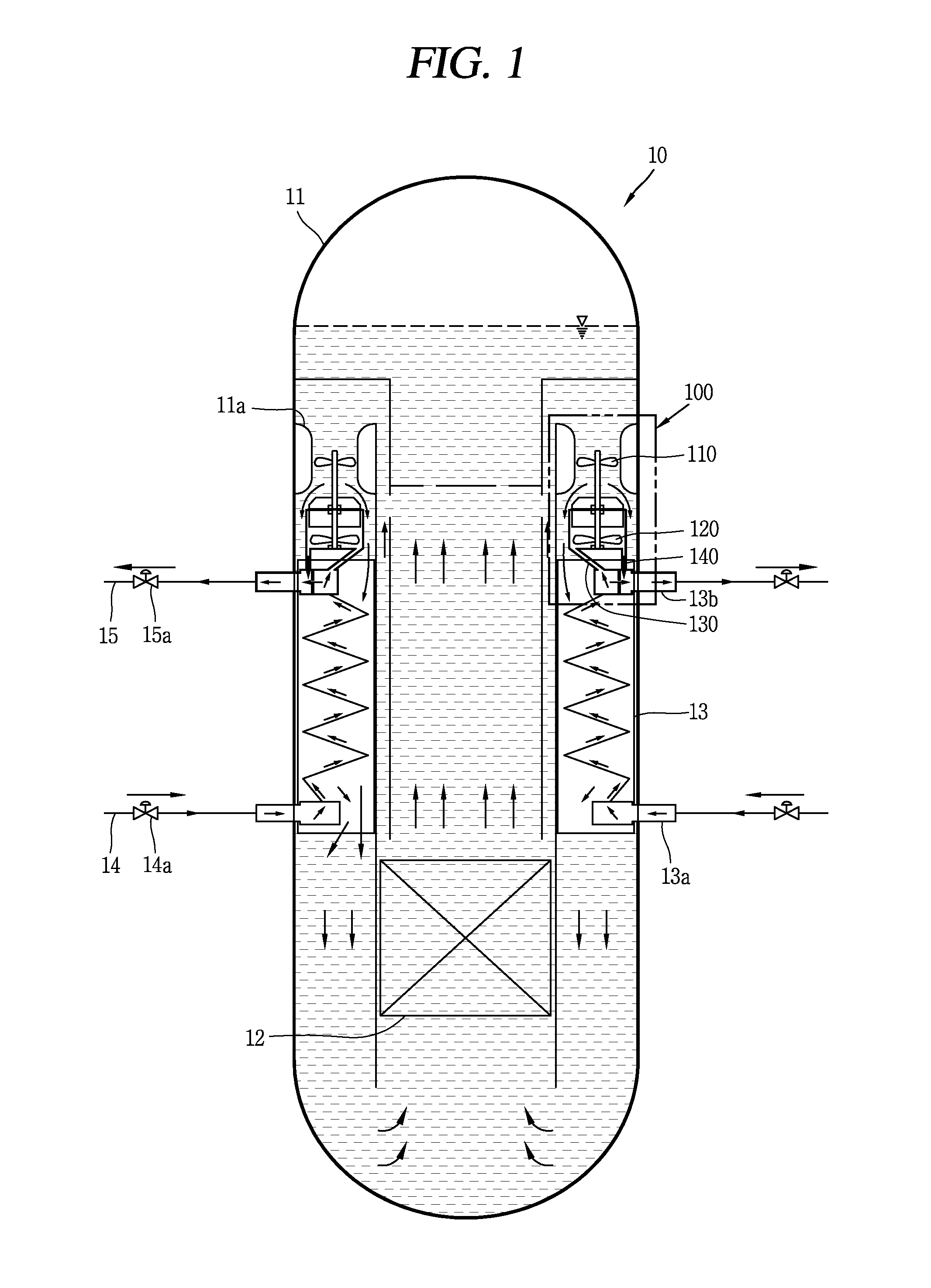
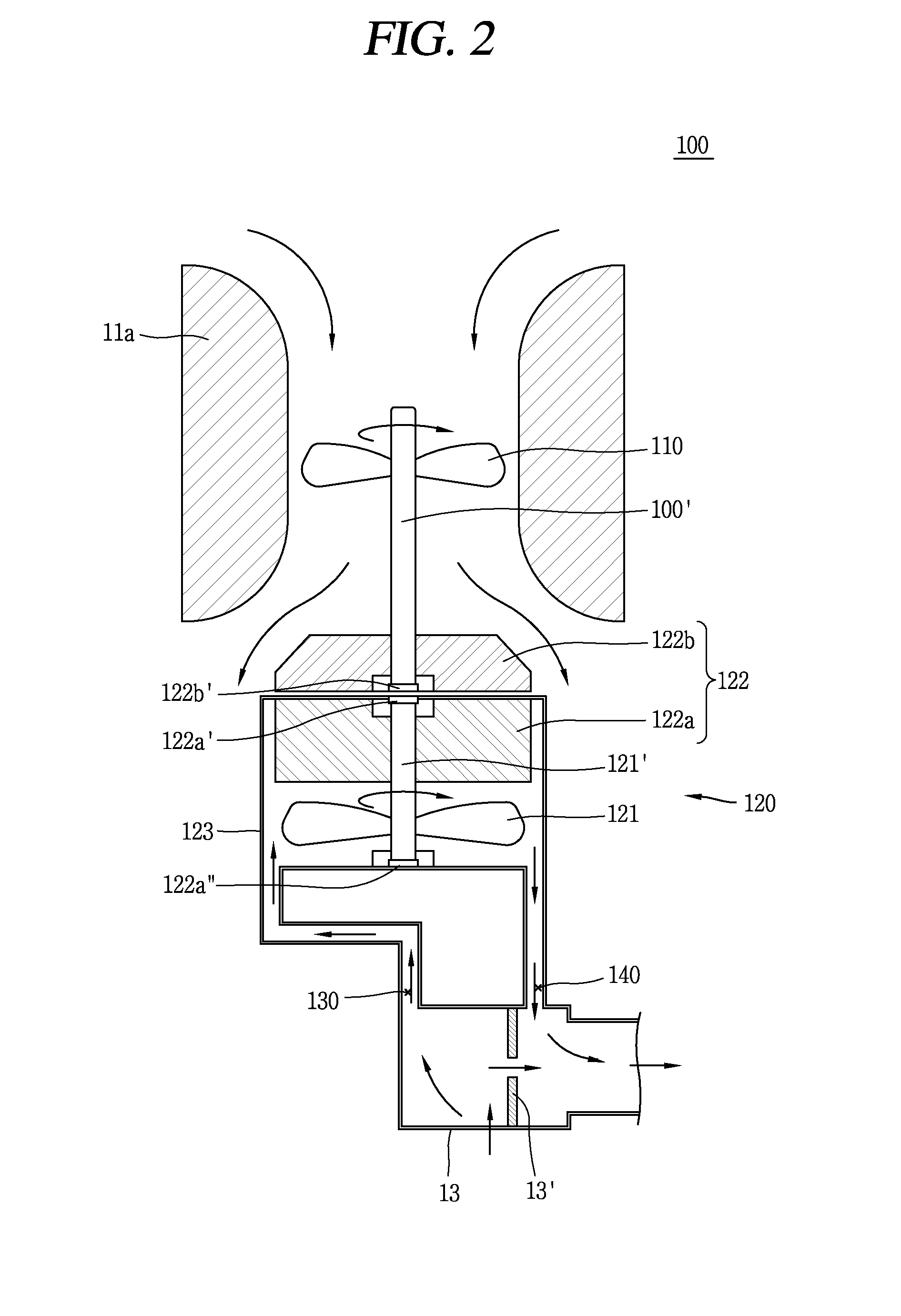
[0039]Description will now be given in detail of a reactor coolant pump and a nuclear power plant having the same according to an embodiment, with reference to the accompanying drawings.

[0040]In this specification, the same or equivalent components will be provided with the same reference numbers, and description thereof will not be repeated. A singular expression in the specification includes a plural meaning unless it is contextually definitely represent...


PUM


Abstract

The present invention discloses a nuclear reactor coolant pump that does not rely on an electric motor, but is operated by means of driving force generated inside a nuclear power plant, so a to be capable of maintaining the safety of the nuclear reactor when the nuclear reactor is operating normally and also in the event of an accident in the nuclear reactor. The nuclear reactor coolant pump comprises: a pump impeller rotatably installed in a first fluid passage of a nuclear reactor coolant system to circulate a first fluid inside the nuclear reactor coolant system; a drive unit receiving steam from a steam generator to generate driving force to rotate the pump impeller, and rotating about the same rotating shaft as the pump impeller to transfer the generated driving force to the pump impeller; and a steam supplying unit forming a passage between the steam generator and the drive unit to supply at least a portion of the steam released from the steam generator to the drive unit.

Description

TECHNICAL FIELD[0001]The present invention relates to a reactor coolant pump driven by steam generated from a steam generator, and a nuclear power plant having the same.BACKGROUND ART[0002]A nuclear reactor is categorized into a loop type reactor where main components (a steam generator, a pressurizer, a pump impeller, etc.) are installed outside a reactor vessel (e.g., a commercial reactor: Korea), and an integral reactor where main components are installed inside a reactor vessel (e.g., SMART: Korea) according to an installation position of the main components.[0003]Further, the nuclear reactor is categorized into an active reactor (e.g., a commercial reactor: Korea) and a passive reactor (e.g., AP1000: USA) according to an implementation method of a safety system. The active reactor means a reactor using an active device such as a pump which is operated by power generated from an emergency diesel generator, etc. in order to operate a safety system. And the passive reactor means a...

Claims


Application Information

Patent Timeline
IPC IPC(8): G21C15/24G21C15/18G21D1/04
CPCG21C15/24G21D1/04G21Y2002/50G21C2015/185G21Y2004/30G21C15/182G21C1/322G21C1/328G21C15/243Y02E30/00Y02E30/30G21C1/324G21C1/326G21C15/247G21C15/28G21C15/185
Inventor KIM, YOUNG SOOKIM, YOUNG INPARK, CHEON TAEYOON, JU HYEONKIM, TAE WANKIM, KEUNG KOOHA, JAE JOO
Owner KOREA ATOMIC ENERGY RES INST
Why Eureka
Try Eureka